


The US heat treatment industry has emerged strongly after two years of COVID-19 restrictions and supply chain constraints. Despite being considered an essential industry and never being asked to suspend operations, it was still impacted by the overall performance of the rest of the economy, especially the automotive industry.
However, there has been robust growth from late 2021 and 2022 that has extended until today. Although there has been some slower growth in Canada and the US Northeast region, the growth of southern states from California to Florida has made up for the slowing heat treatment in the Northern US region.
We have seen five trends in the heat treatment industry and five new trends in heat treatment process application. One trend in the heat treatment industry is consolidation by larger corporate entities, which buy smaller privately-owned heat-treating companies or private heat treaters selling operations to private equity firms.
The aerospace and defense industries are facing fast growth with high demand for airplanes and new weapons for the Ukrainian and Israeli wars. The furnace manufacturers have record sales in 2021 and 2022, but booking in the last three months has slowed but not very noticeably. The SDG and environmental goals are less prominent in the minds of many US heat treaters.
The US heat treatment industry is mostly against government-imposed regulations. Economic efficiency and cost reduction drive technological change in the US heat treatment industry. Examples of game-changing technologies will be discussed. The Metal Heat Treatment Institute (MTI), an association of commercial heat-treatment companies in the US) is predicting an 11% slowing economy in late 2024 and 2025 and recovery in late 2026. Discussion of global issues facing the heat treatment industry and a new approach for attracting younger generations will be presented.
Total US Heat Treatment (Captive and Commercial) – $35.13 Billion
US Commercial Heat Treatment – $5.27 Billion
Number of Commercial Heat Treating Companies in the US – 605
The ratio between Captive and Commercial HT – 85%/15%
Total number of employees in Commercial HT companies – 21,000
Number of Furnace Equipment and Related Components Manufacturers – 298 companies
Total Shippment (NAICS 333994) Industrial Furnaces and Ovens – $2.8 B
Number of Employees (NAICS 333994) Industrial Furnace and Ovens – 10,405.
In Europe, the heat treatment performed in captive and commercial is 80% to 20%, while in Asia (excluding Japan), it is 90% to 10% to the best of my estimate.
The below data are particularly intriguing due to the significant difference in sales per employee. For instance, the US commercial heat-treating shops can have sales ranging from $100,000 to $280,000 per employee. (Bill Jones stated the $280,000 figure in The Monty interview in 2020.) The higher sales per employee are typically achieved by commercial heat treating companies specializing in vacuum heat treatment, vacuum brazing, nitriding, and catering to the medical, defense, and aerospace industries.
Even higher profitability may occur for companies specializing in surface modification processes such as PVD, CVD, and high-end coating. The profitability of the HIP operation depends on loading utilization and a large customer base with similar parts for processing.
Some people compare running a business to bicycling; you must paddle continuously to avoid falling. Life is never easy, but the same goes for business.
Janusz Kowalewski, Ipsen Japan, November 2023
Most vacuum furnace operators rely on the partial pressure option to prevent sublimation, diffusion bonding, and alloy depletion during high-temperature, high-vacuum operation.
The partial pressure with noncombustible gases can operate up to 5 Torr (666 Pa), with the most popular setup from 500 to 1500 microns (60-200 Pa) and with Hydrogen up to 10 Torr. The partial pressure is crucial in various processes, including hardening, brazing, and sintering. Several excellent articles about partial pressure description exist on websites and in heat-treating magazines.
The use of partial pressure segments during burnout cycles has advantages over only deep vacuum setups and should be considered in routine maintenance procedures. Combining partial pressure and vacuum provides a cleaner hot zone in less time.
As per AMS 2769 3.2.4.1.1 Bake-Out Cycle guidelines, the vacuum operator must ensure that the heat-treating furnace meets the contamination requirements of the relevant heat-treating specifications. To achieve this, the operator should carry out bake-out cycles, maintaining a temperature of at least 50°F (27°C) higher than the maximum intended temperature, for not less than one hour. During the bake-out cycle, the pressure should equal or below the intended operating pressure.
The cleaning cycle with partial pressure is very straightforward.
The operation consists of opening a needle valve during partial pressure to achieve the process pressure, then closing it again when the pressure exceeds the SP.
Depending on the supply pressure and the needle valve setting, the delta on the chamber pressure can be large, small, or flat if the needle valve is set just below the SP. The intermittle gas flow gives a sweeping action, as the pumps always pull the gas from the chamber. So, any O2 or outgassing from contamination is swept from the chamber.
The greater concentration of molecules within a given volume leads to an increased frequency of collisions between the molecules and the insulation. As a result, the kinetic energy of the molecules is also higher, allowing for deeper penetration of energy into the refractory. The objective is to eliminate any impurities and thoroughly cleanse the insulation. Therefore, the approach channels energy into the refractory to facilitate its cleaning.
Once the partial pressure segment is complete, the process continues with the vacuum again. The operator should watch the chamber, foreline, and roughing pump pressures. As the vacuum segment continues, these values will drop. When values stop falling, we have removed most of the contamination.
Janusz Kowalewski, Ipsen Japan, November 2023
The Japan Heat Treatment Association has requested that I deliver a presentation on the current state of the heat treatment industry in the United States at the Yokohama IFHTSE Conference.
I have categorized the trends in the heat treatment industry into five HT Industry trends and four HT Metallurgical Process trends. What are the current trends in the heat treatment industry from your perspective? I’m interested to hear your thoughts on the accuracy of these five trends.
Commercial Heat Treatment and Furnace Industries Consolidation.
The commercial heat treatment industry in the US is undergoing consolidation and transitioning from traditional private family ownership to a more corporate style of ownership. Companies like Bodycote, Aalberts, and Thermal Process Holdings (TPH) lead this change alongside private equity firms.
The trend is confirmed by the recent sale of Stack and Lake heat treatment companies to Bodycote.The high costs of upgrading equipment, complying with environmental standards, and meeting industry requirements prove difficult for smaller private companies. Also, smaller furnace companies will need consolidation in the next economic slowdown predicted by 2024-25.
Digitalization, Simplification, and Automation of Heat Treatment Operation.
The upgrade mainly involves improving the control system to enhance convenience, recording, connectivity, accuracy, and controllability, driving the digitization of processes. The digital recording requirements specified in AMS 2750G confirms this trend. The increasing cost and shortage of labor make automation a prerequisite in many operations.
Transfer of Heat Treatment Process and Maintenance Know-How from End User to Vendor (Furnace Manufacturer) Driven by Proprietary Software.
More furnace companies offer proprietary software for maintenance supervision (e.g., PdM Metrisc) and process setting (e.g., AVAC for LPC).
Replacement of High Generating CO2 Furnaces with More.
Efficient Furnaces and Larger Furnace Sizes.
There are furnaces with improved insulation and more efficient heating systems, and vacuum furnaces are replacing smaller sealed quench furnaces.
Increasing Nano and Thermo/Chemical Surface Modification
Processes for Near-Shape Technologies, MIM, and Additive Manufacturing.
The automotive industry increasingly utilizes the FNC process, while MIM and Additive Manufacturing are experiencing steady growth.
Janusz Kowalewski, Ipsen Japan, November 2023
I often receive inquiries from customers who wonder if traditional vacuum furnaces designed for Inconel and Copper brazing can also braze aluminum. Most people believe that if a vacuum furnace has a diffusion pump and can heat up to 1320C, then it should be able to handle aluminum brazing, which only requires a maximum operating temperature of 650C. However, this is not the case, and we’ve compiled a list of reasons why, as explained by Jim Grann, Ipsen’s in-house Aluminum Brazing expert:
1. Special all-metal hot zones are required for aluminum brazing.
2. Opening the door of a VAB (Vacuum Aluminum Brazing) furnace at temperatures ranging from 170C to 534C is impossible in a standard brazing furnace without damaging the hot zone.
3. Square six-sided heating is necessary for aluminum brazing.
4. The standard moly or graphite element and other hot zone components are incompatible with the VAB process.
5. The pumping systems must have faster pumping speeds for the VAB process than a standard furnace.
6. A standard furnace has cold walls, whereas a VAB has a specially designed recirculating heated water control.
7. The main valve on a VAB has special design considerations employed for dealing with magnesium.
Here are some additional points for customers performing vacuum aluminum brazing to consider:
1. Burnouts don’t remove everything but re-vaporize materials, with a small percentage pumped out. The balance of materials being pushed deeper into the shielding and onto the cold walls.
2. How much magnesium can condense on a typical cold wall furnace is surprising.
3. VAB processes seldom go above 704C for clean-up cycles.
4. A standard furnace can reach 1320C, but any leftover aluminum would surely vaporize onto the customer’s fixtures and parts in subsequent processes, which could cause melting problems and eutectic-related issues.
5. VAB elements and insulators are specifically designed to handle the magnesium generated from the VAB process.
When working with aluminum brazing vacuum furnaces, it’s crucial to take preventative measures to avoid maintenance and operational problems. Cold surfaces can attract magnesium oxide (MgO) and magnesium (Mg), which can cause short circuits between resistors and the thermal shielding of the chambers. The oxide creates stubborn deposits that are difficult to remove and still conduct electricity enough to cause short circuits. Removing magnesium deposits can also be hazardous, as magnesium ignites easily in the presence of air and can cause serious injury to operators and maintenance crew. The resulting droplets can’t be extinguished with water and burn at 2000C.
Janusz Kowalewski, Ipsen Japan, July 2023
One of these surface modification processes is Low-Pressure Vacuum Carburizing (LPC) for PM/AM parts. LPC is a non-equilibrium process that constantly changes as the carbon concentration levels on a metal surface change. Unlike in an atmosphere carburizing process, LPC’s carbon potential cannot be measured (because it is conducted under a vacuum between 4 to 10 mbar) and set up to achieve a specific carburizing level and case.
LPC is an empirical process that can be designed through computer simulation software. LPC uses the boost-diffusion technique to manage the carbon content and case depth. In the boosting step, the carburizing gas flow must be sufficient to saturate austenite without causing soot deposition or the formation of massive carbides. The software calculates the appropriate gas flow rate for case depth and carbon concentration.
However, PM/AM parts may absorb more carbon due to larger internal surface pores created. The amount of carbon absorbed depends on the metal’s density, the surface layer’s density grade, and whether it is „as machined” or „as sinter/printed.” Enhanced carbon diffusion results in faster case building, especially when the pores are open and interconnected with low-density surfaces.
Janusz Kowalewski, Ipsen Japan, July 2023
As I travel across Asian countries with tropical climates, I have noticed the challenges of operating vacuum furnaces in high temperatures and humidity above 90%. The recent record-breaking temperatures in June have highlighted the difficulties of running a vacuum furnace. Electrical components cannot function effectively in humidity levels above 90%, which leads to a rapid decrease in efficiency. For instance, at temperatures above 40C (104F), VFD efficiency drops by 2% with each additional degree. High temperatures cause changes in electricity flows, which increase resistance. Additionally, excessive humidity reduces transformer insulation and resistance and oxidizes electrical conductors. The difference between cooling water temperature and ambient temperature with high humidity can cause the vacuum vessel to „sweat,” affecting the entire furnace’s electrical system and transformers’ performance. Here are some tips on maintaining vacuum furnaces:
1. Check and tie all electrical connections. Apply conductive copper grease to improve electrical contact between surfaces.
2. Clean all vents in the control cabinet without the air-conditioning unit. Use silica gel to reduce moisture in a control cabinet.
3. Clean the hot zone, check insulation and ceramics, and repair if necessary. Run periodic burnout cycle.
4. Clean the main O-ring and apply a thin silicon vacuum grease or graphite layer.
5. Check the vacuum oil pump condition and change it if contaminated to avoid solidification during prolonged shutdowns. At high temperatures, vacuum oil loses its viscosity and lubrication properties. Replace oil on timely bases.
6. Check all water and gas connections for leaks and clean them to prevent impurities from forming a hard layer and blocking power feedthrough and flowmeters: flush vessel and heat exchanger with Rydlyme solvent.
7. Apply grease to all points per specification, including cooling motor bearings with proper viscosity.
These steps will help ensure the proper functioning of your vacuum furnace and reduce energy consumption.
A vacuum furnace does not cause excessive heat. The hottest part of the vacuum furnace is the diffusion oil pump, compartment, and mechanical pump. To ensure the safety of their employees, Ipsen requires Heat Stress Training, a 40-minute program that covers the symptoms of heat stress, prevention tips, and first aid procedures in case of heat stress. With climate changes and higher temperatures, Heat Stress training is becoming increasingly crucial for the well-being of workers in heat treatment shops as well. Heat stress early symptoms include:
Fatigue
Cramps
Sweating
Dizziness
High pulse rate
Confusion
Nausea
Red, dry skin
Confusion
The best to minimize the possibility of heat hazards such as heat stroke, heat exhaustion, or heat rash is to drink a lot of water, have frequent cool-down breaks, and wear a light-colored cotton uniform.
Janusz Kowalewski, Ipsen Japan, June 2023
Vacuum furnace manufacturers face increasingly complex operational demands due to evolving heat treatment technical requirements and environmental regulations. Vacuum furnace buyers expect more efficient processes, longer component life cycles, and vacuum furnaces with digital control and self-diagnostic capabilities.
The solution to these expectations lies in better mechanical vacuum furnace design and controls utilizing regenerative AI technology. Below are enhancements that have made a vacuum furnace the preferred option for numerous heat treatment processes and applications:
Janusz Kowalewski, Ipsen Japan, May 2023
Exciting new trends in the vacuum furnace domain. I recently discussed with one of the largest automotive manufacturers in Asia how to reduce the environmental impact of their heat treatment operation. Japan will be declared to be Carbon neutral by 2050. The entire country is making a considerable effort to reach its ecological goal. One Japanese innovation is to use Ammonia as a next-generation clean fuel along with Hydrogen because it burns without emitting carbon dioxide. The correlation between part metal, process, and equipment is my starting point for any environmental discussion. You must discuss one factor by taking to account two other factors. You can improve the process, part metal, or equipment alone, but this will not significantly impact cost or reduce CO2 emissions. An example of substantially reducing the environmental footprint would be changing carburizing to carbonitriding. There are several advantages to running carbonitriding operation compared to carburizing. The carbonitrided surface provides better hardenability, wear resistance, shortened process time, resistance to softening during tempering, and lower process temperature. The trimmed process time and lowering temperature reduce CO2 emission. The disadvantage is limited case depths 0.035in or less (0.9mm) ) and poor impact strength. Steels commonly carbonitrided included AISI/SAE 1000, 3000, 4000, and 8600 series with a carbon content of about 0.25%. Higher carbon content in steel will limit the case to 0.012in (0.35mm). The typical process temperature is 1375-1600F (745-871C). The ferritic soft microstructure is converted to a hard martensitic structure after quenching. At the lower temperature range, carbon diffusion occurs too slowly to be economical.
The Low-Pressure Carbonitriding process is carried out in a vacuum furnace under 10 to 80 Torr and controlled by Ipsen Avac-N® software. Vacuum Low-Pressure Carbonitriding provides additional advantages such as:
•no internal oxidation.
•uniform carbonitriding of parts with small holes, even blind holes.
•combination of the carbonitriding process with high-pressure gas-quenching eliminated the need for post-washing.
•low gas consumption of Acetylene C2H2 as the source of Carbon and Ammonia as the source of Nitrogen.
Overall, environmental heat treatment transformation includes:
Ipsen has continued to guide the environmental evolution by providing innovative vacuum heat treatment equipment and processes.
Janusz Kowalewski, Ipsen Japan, May 2023
Duplex coating technology is based on a combination of nitriding and thin film deposited by PVD or PACVD technology (TiN, TiCN, TiAlN, TiB2, etc.). Because the adhesion of the layer on the metal substrate is given only by inter-atomic forces, one of the conditions for its maximization is a metallically clean surface, without oxides, which allows strong bonding between atoms at the layer and nitrided substrate interface, ie between TiN, TiCN and tempered martensite of coated tool.
Thus, the substrate itself is usually in the form of tempered martensite, a supersaturated solid solution of carbon in iron α. However, during nitriding, interstitial nitrogen is also deposited in the lattice, thus creating a doubly supersaturated α´-Fe (N, C) structure, with a nitrogen content of 0.0 – 5.9 wt% and a carbon content according to the chemical composition of the steel and the degree of martensite tempering. For high-alloy HSS steels also with a certain content of cementite and MC, M2C or M6C carbides [1]. By incorporating nitrogen into the α-lattice, the compressive stresses in the nitriding layer increase significantly, on the order of several GPa.
One of the things I’ve learned over time is that tool makers or die casters don’t know, or don’t want to know, that they should be auditing their heat treatment suppliers. And if they already know that, which is based on the CQI-27 application, then they don’t know how to do it.
This is understandable, because the field of heat treatment and material engineering is completely outside the scope of their core business. Either the technology of die-casting or the manufacturing of tools for high pressure die-casting (HPDC).
So how to do it? Here is a rough guide. In order for the audit to fulfil its objectives, it must be comprehensively focused on the entire activity of the heat treatment plant.
Heat treatment plant audit for Nadca 207
As energy costs rise, the importance of furnace consumption rise as well, whether in natural gas or electricity. However, if we are going to buy a refrigerator or a washing machine, we have EU energy label on it showing that the appliance works in class A +++ -.
But what about heat treatment equipment? When investing in new equipment, we usually find out from the offer what the total input of the furnace is, sometimes added information about the input of the cooling turbine or vacuum pumps, input for oil bath heating etc. However, these are the data we need to dimension the cable or circuit breakers and fuses. However, we usually do not receive any information about the actual consumption. And when we ask about it, we usually get strange information from furnace manufacturers, which usually indicates their detachment from reality. At the same time, for example, in a well-managed heat treatment plant, one of the KPI indicators is the sales per 1 KWh of energy consumed, or to calculate the cost of the quotation process, we must know at least the average equipment consumption so we can calculate cycle costs and then set the quoted price.
An integral part of die casting dies manufacturing process is annealing. Its purpose is to relax stresses, caused both by different types of machining and by the actual use of the tool. What does this mean for tool production?
Each insert of dies should go through the following processes:
Drafting drawing Purchase of Material
1. Input material testing (hardening in the oil)
2. Stress relieving after machining (600-650 C)
3. Hardening and 2 or 3 tempering cycles including material testing after quenching
4. Stress relieving after EDM (500-550 C)
5. Pre-heating for welding and stress relieving after welding (500-550 C)
6. Post-oxidation of critical inserts before sampling
7. Stress relieving after sampling (500-550 C) or
8. If nitriding is prescribed, then this process (450-550 ° C)
9. Stress relieving of stresses from thermal fatigue after 1000-2000 shots
10. Stress relieving of stresses from thermal fatigue after 5000-10000 shots
11. Stress relieving of stresses from thermal fatigue after 10000-20000 shots
It can be seen from the above list that annealing processes are of great importance in die making. Only up to step 8 is the tool manufacturer responsible for securing them. However, since the condition for the delivery of the tool according to Nadca 207 is the necessary traceability of all activities, the tool manufacturer must provide all the required documentation for these operations.
Steps 9 to 11 are then up to the user of the tool. However, if during the life of the die it is necessary to perform any additional machining on already hardened parts, e.g. due to shape repair, it is necessary to add even more annealing processes. After milling, EDM, welding, polishing, etc.
Stress relieving processes reducing thermal fatigue stress are shown in Fig. No. 1 at bottom, including their recommended periodicity. This periodicity is approximately consistent with the repeated nitriding processes as recommended by Nitrex for extrusion tools. In both cases, there is a common interest in limiting tensile stresses in the surface layer, promoting crack formation and propagation.
how to perform annealing for die casting dies
In parts I and II, I described the heating phases, the aim of which is to heat up the parts to the austenitization temperature and then to homogenize them well before the quenching itself. These heating phases must take place automatically, without the intervention of the furnace operator, and regardless of the size or shape of the parts.
Similar requirements are for the cooling phase, resp. for quenching, when we need to cool down the parts quickly from the austenitization temperature. This sequence of the processing cycle must also take place automatically, without operator intervention, and regardless of the size or shape of the inserts.
If we have a furnace in which we can control the hardening cycle with Ts and Tc, we have correctly placed load thermocouples Ts and Tc, then the secret of optimal cooling lies in the correct evaluation of these temperatures and in monitoring their temperature difference dT = Ts – Tc. As with heating, it must be taken into account that the hardened steel with temperature above about 500 °C is in a plastic state, below this temperature in an elastic state. Below ≈ 500 °C, we must also take into account the stresses from the temperature difference, and below ≈ 300 °C, the transformation stresses from the change from austenite to martensite are added to this.
At the same time, we must know the CCT diagram for hardened steel so that we can exclude structural phases that reduce the impact strength of quenched and tempered steel. This is mainly an undesirable precipitation of carbides, as well as the proportion of bainite or perlite in the structure. Thus, so we have to control the cooling to miss the area of carbide precipitation for a given steel 1, and at the same time so that we do not enter the area of bainite at all or minimally.2. However, since the carbide or bainite precipitation curves are individual for each steel, the hardening process should be modified with respect to the type of steel being processed – see Figures 1 and 2 for H11 and Dievar steels.
Heating of dies in vacuum furnace part II
Jiří Stanislav, September 2021
Sometime more than 20 years ago, I tried to find a model that I could show to the customer, and which could specify exactly why the shaped insert made by them cracks during hardening. So, we created a hardening model of insert from high alloy steel with a medium thermal conductivity of 30 W/mK, size 600×400 mm, hardened from an austenitizing temperature of 1050 C and cooled to a temperature of 20 C. For modelling was used Deform simulation software. Two cases were studied. The first with a notch in the middle of the bottom of the insert and with a radius R0, the second with the same shape but with a radius R10. The aim of the simulation was to clearly show 1) where the maximum of tensile stresses is and 2) what is the effect of radius size on stress. .
. 
Fig. 1 – Computational network for radius R0
Fig. 2 – Computational network for radius R10
The result is shown in Figure 3. As expected, the greatest tensile stress is at the notch. Other tensile stress maxima are on the outer side of the insert, i.e., in places that most designers believe are not significant. The crack in the notch propagates at an angle of about 45 ° as a result of the superposition of tensile stresses in the “x” and “y” directions.


Fig. 3 – Tensile/compressive stress distribution during cooling from the hardening temperature
Fig. 4 – A practical example showing the concordance of a model on a real part made of material 1.2379
In terms of the result, I consider it most important that the model clearly shows that the critical points for hardening are on the outer side of the insert. In the middle of insert, where the designer places the shape of the final product, and which will then be the result of the injection or forming process, there are usually compressive stresses. These are not dangerous in terms of hardening. But it is precisely the cavity of the insert that the designer focuses on, because he wants his product to be exactly as it requested. But that often not enough. It is the outer side of the insert that is the source of danger and critical cracks, and it is up to the designer how to deal with it.


Fig. 5 – Example of a crack due to incorrect mounting of the inlet insert
Fig. 6 – Example of a crack formation from a clamping groove made without a radius
And what is the effect of the radius? Figure 7 shows the tensile stress at the notch for the radius R0, and Figure 8 shows the radius R10. From about 1150 MPa, the tensile stress drops to 780 MPa, i.e., by only 23%.


Fig. 7 – Tensile stress in “y” direction for radius R0
Fig. 8 – Tensile stress in “y” direction for radius R0 R10
So, the basic rule applies. To prevent the parts from cracking, we must eliminate all notches on the outer side of the insert, and at the same time we must apply the maximum possible radius. This is especially true for die casting inserts hardened according to Nadca 207, where we must cool for at least 28 C/min, regardless of stresses and deformation, because we have to achieve the correct internal martensitic structure of the material. It is then up to the designer how to treat these risks. The solution is also a two-step drawing, one for the preparation of the insert for hardening and the second for final shape. Of course, we must not forget about the quality of the material, but that is another chapter.
Jiří Stanislav, June 2021
What is the optimal ratio between hardening and tempering furnaces?
Almost every day I learn from various sources that someone is selling to someone or someone is buying a new vacuum hardening furnace somewhere. However, information rarely appears about how much has been invested in tempering furnaces. So, let’s look at how it works in practice in a commercial heat treatment shop. The typical structure of processed steels is shown in the picture, while the categories of steels for hot work, cold work, HSS or powder steels require at least 2 tempering cycles, but today usually tempering 3, in extreme cases even 4. Together, this is almost 82% of the steel quantity that enters into commercial vacuum heat treatment shops.

Fig. 1 Portfolio of individual types of steels typical for vacuum heat treatment shop
We will make a simple case analysis of the revenues and costs of vacuum heat treatment. The average price for hardening and two tempering on the European market is € 2/kg. The basic dimension of vacuum hardening and tempering furnaces is 600x900x600 mm, furnaces are up to 800 kg. To calculate the costs, we can take the following rates: hardening furnace € 30/h, tempering furnace € 10/ h. In terms of time, if we take into account the usual average batch up to 300 kg, we will fit with each hardening and tempering cycle within about 8 hours.
So, we are able to perform hardening and two tempering cycles within 24 hours. An important condition of this work rhythm is the prescription of the number of tempering cycles and the number of tempering furnaces for this operation. In our case study, we will compare 3 variants. 1) we have a hardening furnace and therefore hardening and two subsequent tempering are performed only in this furnace, 2) we have a hardening furnace and one tempering furnace of the same size, 3) we have one hardening furnace and two tempering furnaces of the same size. We calculate revenues and costs for batches of 100, 200, 300 and 400 kg. The yield is easily calculated, because we multiply the weight of the batch by the price per kg, i.e. 100 x 2 = € 200, 200 x 2 = € 400, 300 x 2 = € 600 and 400 x 2 = € 800.
For costs, we take the basic cost rate for the 100 kg batch, which we increase by an increase in energy and nitrogen consumption by 4% for every 100 kg of charge. The length of each cycle is always 8 hours.

And what is the result?
Variant 1) – we only have a hardening furnace. In this case, we perform tempering in the most expensive equipment, which is also not suitable for tempering with regard to the design of the furnace for high temperature operation, necessary for hardening. Although equipped with convection heating, tempering in a hardening furnace usually does not achieve the same performance as tempering furnaces equipped with a powerful fan for conventional gas heating. It can be seen from Figure No. 2 that even with a load of 400 kg and a price of € 2/kg, we will always harden with a loss. We can say that we will process batches over 500 kg, but the cycle times will be significantly extended and we will not fit into the 24-hour cycle. At the same time, however, we must also take into account the required cooling rates, e.g. according to NADCA, where the furnace should not be loaded above 50% of the permitted weight so that this cooling rate can be achieved (so-called load fill rate).


Fig. 2 Costs and revenues for processing H + 2T in the hardening furnace
Fig. 3 Costs and revenues for H + 2T processing in hardening and tempering furnaces
Variant 2) – we have one hardening furnace and one equivalent tempering furnace. The critical limit becomes a load of about 240 kg. We are already making a profit above this weight. However, sales for this set of furnaces will not be high, because due to the requirement for 2 tempering cycles, the furnaces cannot be used full time.
Variant 3) – one hardening and two tempering furnaces of the same size significantly improve our performance. We get to the profit already at a load of around 220 kg, as it is in the Figure 3. The advantages of this configuration are in time planning, and especially in the utilization of equipment. The hardening furnace can perform 3 hardening cycles per day, so we can effectively harden non-stop, and the two tempering furnaces ensure corresponding tempering cycles, also with maximum utilization of the furnaces. This significantly brings an increase in sales and higher return of investment (ROI). As can be seen from Figure 4, this is a step change, when the theoretical annual turnover rises from 5.7 Mil. CZK for variant 2 to CZK 13.4 million. This is an increase of 235%.


Fig. 4 Costs and revenues for processing H + 2T with one hardening and two tempering furnaces
Fig. 5 Theoretical annual sales for variants 1, 2 and 3
If we compare all variants according to economic aspects, then only for variant 3 we get the payback of the investment under 6 years. In terms of ROI, we have an estimated ranking of 10%, 12% and 23%. Thus, only the variant of one hardening furnace and two tempering furnaces gives us the certainty of good economic parameters of the investment, but above all, good customer service level, meeting the customer’s requirements for pricing, delivery time and quality.
Jiří Stanislav, April 2021
Temper furnace selection and carbon footprint
What should such a tempering furnace look like? There are two basic solutions. Retort furnace and non-retort furnace with direct batch heating. Those who want to purchase equipment only for tempering should know that a furnace with a retort consumes 30% more energy for the same job, ie for tempering, than a furnace without a retort.

If we calculate the service life of the furnace at 20 years, then the retort furnace consumes extra energy during its life, comparable to its acquisition value. But not only that. Because 0.256 kg of CO2 is created per 1 kWh of energy consumed, a huge amount of CO2 is created during the life of the furnace. The calculation is simple. The average hourly input of the tempering furnace with a retort, size 600×900 mm, loading 200 kg, is approximately 25 kW. Cycle time 8h. At 80% annual utilization of the equipment, the consumption is 365 * 24 * 0.80 = 7008 Nh * 25 kW = 175 200 kWh. If I temper in a furnace without a retort, the energy consumption will be 30% lower (see diagram), so I will save 52,560 kWh per year. With an energy price of € 0.20 / kWh, this is an annual saving of € 10 512. In the 20 years of the furnace’s life, it is saving of € 210 240
If we convert this amount to a carbon footprint, then in these 20 years the furnace without retort will reduce the amount of CO2 by 52,560 * 20 * 0.256 = 269,107 kg of CO2. It’s an incredible number. I understand the importance of retort furnaces where diffusion processes are involved. Nitriding, carbonitriding, etc. There is this irreplaceable solution. But if I really only want this device for tempering, then I make a huge mistake and I’m not sure if I’m always aware of it as an investor.
So if we are not very environmentally friendly, and we don’t care how much extra CO2 we produce, we should in all circumstances think about the economic conditions of heat treatment so that the customer gets its value at a good price. And I’m not really sure if everyone really wants it.
Jiří Stanislav, February 2021
Vacuum furnaces are one of the most environmentally friendly equipment within a heat treating shop. But does not mean they are free from safety concerns. For example, the usage of Acetylene (C2H2) and Ammonia (NH3) in vacuum furnaces during the Low-Pressure Carbonitriding may create hazardous conditions. The mixtures of Acetylene and Ammonia in some rare cases may produce Hydrogen Cyanide. Hydrogen Cyanide (HCN), sometimes called Prussic Acid, is an organic compound with the chemical formula HCN. It is a colorless extremely poisonous liquid that boils slightly above room temperature, at 25.6 °C (78.1 °F) When the reactant ratio (Ammonia to Acetylene) is below or above a critical value, the extent of reaction is negligible. But when the critical ratio is correct, high conversions can be obtained generating poisonous gas and creating very hazardous conditions. Also, if there is moisture in the vacuum furnace, Ammonia will react rapidly with copper, zinc and many alloys and corrode them. Double vacuum pumping, Nitrogen purging, vacuum pump gas ballast connected to Nitrogen should be included in process set-ups.
Janusz Kowalewski, January 2021
Vacuum furnace hot zone life depends on the process requirements. Some processes are harder on the insulation than others. The below 8 procedures can help extend hot zone life:
1. Keep leak-free. Check your leak-up rates weekly. 2. Do burn-out cycles on a regular basis. This should be a recipe that goes at least 100F over your typical process temperature. 3. Keep the furnace clean! Metal debris can easily burn into the heating elements and insulation during heating causing premature damage to the graphite. 4. Clean/dry your process parts. Excess oil or cleaning fluids can cause poor pump downs and add to graphite insulation deterioration. 5. Keep cooling gas pressure at minimum required by material and parts thickness. Try step-down quenches, high pressure for the first few minutes then drop the pressure down for the remaining cool. 6. Load gently. Checking all the heating element hardware for tightness/breakage along with checking for loose insulation retaining pins. 7. Make sure bungs and nozzles are restriction free. If there are restrictions, then a quench gas will be forced to go behind the insulation breaking it and blowing retaining pins. 8. Keep the vacuum in level to avoid alloy sublimation.
Janusz Kowalewski, January 2021
Cooling speeds and uniformity are some of the most important operating features in vacuum furnaces. Metallurgical, mechanical, and distortion of the entire load and individual parts will depend on effective and uniform heat transfers during the cooling segment. The inherent gas flow’s instability in vacuum furnaces can lead to non-uniform hardness, excessive distortion, and a mixture of metallurgical structure within the part and the load. Load configuration, parts spacing, cooling gas pressure, gas type (Nitrogen, Argon, Helium, Hydrogen), gas velocity, gas flow pattern, fan wheel design, heat exchanger design, cooling nozzle shape, and size and locations (bung designs in a square hot zone) impact cooling speeds and uniformity. One of the least discussed and understood parts are the cooling nozzles. The nozzle design, spacing between the nozzles, and the nozzle locations have an impact on the speed and cooling uniformity. Several cooling studies have shown that increasing the number of nozzles beyond the optimum number has a diminishing impact on cooling speed.
Janusz Kowalewski, December 2020
Some vacuum furnaces are used for very harsh and highly contaminating processes. One of the processes performed in a special design vacuum furnace in this category is chromium purification. The process is brutal on vacuum furnace components such as graphite insulation, ceramic, heating elements, and vacuum pump systems. The process has three stages: bidder burnout, purification, and furnace cleaning. Bidder burnout: When the furnace reaches temperature 1550°F (843°C) most bidders is taking out from chromium briquettes and pumping out from the furnace. Purification: At around 2000°F (1093°C) the carbon and oxygen start to react and combine and create carbon dioxide and carbon monoxide. This is where the purification happens and the gases are driven out of the chromium. The soaking temperature of 2300°F (1260°C) is where the carbon and oxygen reaction is most effective. The soaking lasts several hours. After the purification, cleaning process starts, chromium molecules are removed from graphite insulation and heating elements. Predictive maintenance and frequent burnout cycle at 2400°F (1320°C) is highly recommended. Monitoring the vacuum level timing is the best guideline for the burnout frequency.
Janusz Kowalewski, December 2020
The vacuum furnace industry is diversified with 6 countries dominating the vacuum furnace industry. But if you look for innovation the number of countries shrinking to mercy 3 countries provides most (but not all) innovations. Some of the past decades were instrumental in vacuum furnace advancement. In the 1970’s we saw the first development of High Pressure Quench in vacuum furnaces. Credit should go to a French company (today not existing) for the introduction of 2/3 bar pressure quench followed by Ipsen introduction of 5 bar pressure. 1990’s industry developed new insulation, implemented LPC using acetylene on mass scale, credit should go to Moscow Lomonosov University, JC Hays Japan (today IHI Group) and Ipsen. For the list of innovations in the vacuum furnaces please scroll down.
Janusz Kowalewski, December 2020
Heat Treatment and Additive Manufacturing
Some AM parts require vacuum heat treatment. Below are suggestions how to enhance AM techniques to optimize heat treatment: 1. Increase the load density. Optimize available surface space to have as many parts on a single plate as possible. 2.AD parts’ thin walls dictate the loading position’s support and fixtures design. Loading should be designed in vertical positions with the help of minimum numbers supporters. 3.Relatively low wall thickness increases the efficiency of heating up but also creates challenges. Setting up cycle parameters such as heat up rate and cooling speed should be very precise so it will not adversely affect the parts. 4.Loading techniques for parts with high and thin walls. Components should be loaded vertically (in same cases under an angle) with 10 mm spacing between parts. 5.The vacuum furnace for alloy materials such as Titanium, Nickel, Cobalt, Tungsten, and Cobalt-Chrome-Molybdenum metal hot zones are recommended. For high-temperature applications above 1400°C Tungsten could be used. For tool steel, graphite hot zones are acceptable. 6.The furnace should have the capability to cool by different gases according to the alloy requirements.
Janusz Kowalewski, October 2020
Before Purchasing a Vacuum Furnace
To be competitive in the market, manufacturers should consider true vacuum furnace ROI before making the final decision. With many solutions available, it’s important to calculate a vacuum furnace’s true ROI before making a purchase. While many solutions are appealing because of the price, investing in high-performance vacuum furnaces can ultimately facilitate a better, more profitable solution for your business. Oftentimes an ROI analysis only focuses on furnace price; however, there are a number of technical and service related features you should examine in-depth in order to determine a vacuum furnace’s true value. It is important to remember warranty is not insurance against furnace breakdowns. Free parts replacement does not make up the cost of lost productivity. The ability to use the furnace without breakdowns is more valuable that free part replacement. ROI evaluation: 1. Operating cost, 2. Maintenance and Repair Interval, 3. Parts Replacement Frequency and Reliability, 4. Service and Spare Parts Delivery Time.
Janusz Kowalewski, October 2020
2021 HEAT TREATMENT MARKET TRENDS
How to Shorten a New Furnace Installation
Many customers are asking how they can shorten a new vacuum furnace start-up. Some customers are choosing to install their own furnaces themselves and only start-up and training rely on OEMs. Here is the short list of preparation: 1.Make sure the floor level is leveled correctly. Level and anchor vacuum furnace and pumps. 2.Flush gas piping and buffer tank with nitrogen before connecting to furnace, then pressurized and check for leaks. 3. Connect and check the water and air systems for leaks and pressure. 4. Remove protection coating from flanges, clean grooves and O-rings with ethylene alcohol and grease it with silicon. 5.Check EMF interference. 6.Make sure all electrical wires on the furnace are securely connected and motors are rotating correctly and have correct voltage.7. Check wiring in the control cabinet for solid connection. 8. Make sure electrical components are set for a correct voltage 120/220V.
to be continued…
Janusz Kowalewski, September 2020
Graphite or Metal Hot Zone?
We all love graphite insulation in hot zone and heating elements in the vacuum furnaces. Industry is selling more graphite type furnaces that all metal hot zone, but that not mean all metal type furnaces doesn’t have advantages and in many cases necessities for some processes and material. Graphite material is easy to work with, come in variety of style, purity, thermal conductivities. What you are looking as furnace designer is dimensional stability, smooth surface, low ash content and low and uniform thermal conductivity through entire insulation sheets. Graphite is hygroscopic material and is prone to absorb water from air causing outgassing and slowing the pumping time. Surface graph foils or inner foils sheets minimize water absorption and then outgassing. All metal hot zones offers higher vacuum level, faster heating, pumping, and quenching (limited gas cooling pressure). All metal hot zone requires higher heating power in the long run because of increases heat losses due to shielding contamination. With proper shielding distancing and spacing, polishing first shield surface and proper maintenance all metal hot zone may reach near graphite insulation efficiency. Materials and processes sensitive to even smallest traces of oxygen requires metal hot zones.
Janusz Kowalewski, September 2020
Future of Warranty
In the US, the average warranty cost in all warrantable equipment is 1.4%. In the heat treatment industry, warranty is an integral part of what we do. How we handle and respond to warranty claims differential vacuum furnace manufacturers into best, good and ugly categories. The rapid heating/cooling pressure changes, corrosive/harmful evaporation, oxidation, and contamination characterizing vacuum furnace operations are imposing on internal parts stresses, degradations and eventual parts failures. Constant cycling of furnace conditions create engineering dilemma for designers to choose correct design/material and how to monitor the part performance. Here is the good news: Vacuum furnace is assembled from around 450 identifiable parts (some parts are in numbers) and critical parts could be traced, recorded and analyzed.
Janusz Kowalewski, September 2020
OPTIMAL HEAT TREATMENT OF HOT WORK STEELS FOR DIE CASTING
The heat treatment of hot work steels for die casting is vacuum heat treatment application which requires a special attention. The final mechanical properties are influenced by many parameters related to the steel selection, manufacturing process, heat treatment and in special cases to the surface modification. The inseparable parts of problem are testing methods. The paper deals with principles which should be used in standard praxis which non-compliance results in low tool life or legal problems in supplier-customer relationships.
Heat treatment of hot work steels is one of the most demanding disciplines in the field. Not only in terms of its own procedures, but above all in terms of determining and adhering to process parameters to achieve optimum service life result with important variability in heat-treated parts. However, when selecting process parameters, it is always necessary to take into account what procedures are ordered and what procedures are usual.
And there is a contradiction between the tool manufacturer’s requirement for tool life and the ordered or usual routing. It is a paradox that the client does not have the usual procedures, or has no knowledge of them, on the other hand, this is what the client requires from heat treatment supplier.
Of course, the next comprehensive chapter is tool design, material selection and hardness, or the way the tool is used in production, but in this article, we will assume that this customer has already investigated and aligned with the usual routings and the best praxis.
Although the group of hot work steels is extensive, basically the same input control is required to all grade of steels. Its definition is implemented in NADCA-207, rev. 2016 [1]. While this definition is primarily intended for die casting molds, it can generally be applied to other applications such as forging dies, extrusion dies, the tools for rolling or hot pressing.
From the point of view of initial testing, the control of chemical composition is a basic, but not decisive, condition. The resulting mechanical properties are determined primarily by the micro-purity, grain size, amount and distribution of primary carbides. From this point of view, in order to distinguish precisely these effects, the usual procedure is to examine the input quality of the material by impact tests measuring the toughness.

It has been shown that the higher toughness of the material is affecting higher resistance of the material to thermal fatigue cracking. A higher impact strength value can also positively affect the formation of macro-cracks associated with tensile stresses.
Impact tests are performed on samples ideally quenched under oil cooling conditions and the measured values should reach the values defined by NADCA-207, rev. 2016 (Tab. 2). If the predicted values are not reached, it is the responsibility of the material supplier to replace the supplied material with a material that would provide the required parameters.
Impact tests are carried out on samples with the least suitable fiber direction to ensure that the limit mechanical properties of the material are evaluated.

3. Heat treatment
The heat treatment of these steels should be carried out according to generally known, conventional procedures. The question is what is meant by these usual procedures. There are no Czech standards for most modern steels, only steel supplier’s material sheets exist. The exception is NADCA-207, rev. 2016 [1], but it is only a recommendation for members of the Association of die casting in the USA.
A properly conducted heat treatment process should ensure that the expected mechanical properties of the input material are achieved. Leaving aside the possible problems with deformation during heating, the most important phases of heat treatment are austenitizing and cooling.
The austenitizing should ensure, on the one hand, the correct dissolution of carbon in the matrix, the partial dissolution of carbides, but on the other hand, it should not allow an excessive growing of the austenitic grain compared to the initial state. These two requirements are contradictory and it is necessary to choose a compromise solution linked to the austenitizing time and temperature, and considering that we heat the 3D body in a heterogeneous vacuum furnace environment.

If heat treatment according to the NADCA-207 specification is not required, the temperatures determined by the steel manufacturer are considered as normal temperatures (green field). If the heat treatment is required in the conformity to NADCA-207, then these temperatures are within the allowed NADCA-207 range (orange field), usually at its lower limit (Table 3).
Higher austenitizing temperatures provide better solubility of the primary carbides, but these carbides precipitate during cooling (quenching in a gas stream) along grain boundaries and reduce the resulting toughness of the material. Paradoxically, due to the higher solubility of carbides, higher austenitizing temperature means higher resistance to self-tempering during use of steel at the working temperature of the tool (Fig.1), greater resistance to thermal fatigue cracks, but at the same time a great risk of grain growth with corresponding lower toughness.

In addition to the temperature and the austenitizing time, a cooling rate is also important, which reduces the possibility of precipitation of these carbides. Higher temperature also reduces Ms and increases the amount of residual austenite in the matrix due to more enriched austenite. This residual austenite is then transformed into not tempered martensite, which reduces toughness.
The second most important parameter of austenitizing is the time. The holding time at the austenitizing temperature must be sufficient to homogenize the austenite, while also partially dissolving the carbides, but it must not allow excessive, uncontrolled growth of the austenitic grain. The higher the temperature, the shorter austenitizing time should be. In case the usual heat treatment is required, it is necessary to follow the instructions of the steel producers. In the case of the NADCA-207 heat treatment, the austenitizing time is the time prescribed as 30 minutes from the complete warming of the part to the end of the dwell under the following conditions (Fig. 2):

Ts (Surface) = Tp (Programmed) and at the same time Ts (Surface) -Tc (Core) < 14 C
If the furnace is not equipped with a temperature measurement by 2 load thermocouples Ts and Tc, the maximum holding time at the austenitizing temperature is limited to 90 minutes from point when Ts = Tp
In order for this parameter to be objective and controllable, the location of the thermocouples must be defined in addition to the above conditions. The tool manufacturer is responsible for making the correct holes for Ts and Tc thermocouples. (Fig. 3).
A very important parameter of the process control is the cooling rate in the area between the austenitizing temperature and reaching a temperature of about 400-450 °C. This should be a controlled parameter with a minimum speed of 28 ° C / min. Only under this condition can the carbide precipitation area be missed for H11 (1.2343) and H13 (1.2344) materials, meaning deterioration of impact toughness of the material (Fig. 4).
The temperature range between the austenitizing temperature and about 500 °C is not dangerous for the formation of cracks, the material is still plastic in this temperature range. Below 500 °C, however, it becomes solid and the material is subject to stress due to the temperature difference between Ts and Tc. This is the reason for applying the isothermal period.

In order for the material to survive this high cooling rate without cracks and extreme deformations, it is necessary that its shape be adapted to this objective. More important for the further development of the service life, more than deformation, the structural properties of the material are achieved by heat treatment. Carbide precipitation and extreme austenitic grain size growth are one of the basic sources of failure. In some cases, extreme grain growth may also be due to the inhomogeneity of the raw material.
All parts for high speed cooling must be designed with minimum radius R3-5 mm on all critical shapes, surface roughness must be treated after machining, and no notches must be created to concentrate stress. Thus, it is on tool manufacturer to prepare its parts with correct design so that they can undergo a high-speed cooling process, regardless of deformation. Otherwise, any exception to this rule can cause and usually lead to a deterioration of the mechanical properties of the steel. It should also be noted that the greatest tensile stresses leading to large cracks are on the perimeter of the mold, not in the shape that creates the product itself
The cooling rate is not usually prescribed, and the choice is therefore up to the heat treatment supplier except when the heat treatment is ordered by NADCA-207. Since this parameter is not generally mentioned on the material sheets, it is very difficult to speak about the usual parameter. Therefore, in order to make a clear distinction as to whether this parameter was chosen appropriately or not, a more objective evaluation of the heat treatment by means of impact tests must be carried out.
After hardening, the material must be tempered at least twice. Despite all efforts to complete the martensitic transformation, the material still contains a large amount of residual austenite. Firstly, it is given by the position Mf and secondly because it is a 3D body with heterogeneous temperature distribution inside. When the surface is cooled to 70°C, inside the body even more than 50% of the residual austenite may be present. The question is therefore when to start the first tempering when the transformation of austenite to martensite is not yet complete.
The usual method states that as soon as possible after quenching, once the part reaches a surface temperature of 50 -70°C. The problem, however, is that during cooling at low temperature, the greatest risk of cracking is due to the fact that we are below Ms and there is a superposition of stresses from both temperature difference and phase transformation. Therefore, the gas cooling in the furnace is usually applied until Tc = 150°C (some steel manufacturers recommend cooling in the furnace up to Tc =100°C), then only in free air. Time to reach Ts = 50°C is then attached to the weight and die shape and can be much longer than “as soon s possible”.
Therefore, the definition of time to first tempering is an abstract concept and cannot be considered as a predefined parameter. However, after quenching the surface temperature must be controlled even after the part has been removed from the furnace. For this reason, a magnetically clamped (usually bimetal) thermometer is placed on the parts and the surface temperature of the part is measured while cooling off the furnace. There is (usually) no record of this phase of the process.
After reaching the surface temperature Ts = 50°C the first tempering can be started. However, this period can take several hours for large tools. Also, the view of this temperature Ts = 50 °C is different between NADCA-207 and some steel producers. For this reason, the usual procedure will vary according to the client specification and may also vary according to the type of material used.
The tempering must be carried out at least twice, taking into account the not tempered martensite resulting from the transformation of residual austenite after the first tempering. For more demanding applications, however, it is better to temper all of the structural components at least twice and therefore triple tempering is needed.
As important is the input control of the purchased material to avoid future disputes, so is the output control after heat treatment. The check is again carried out by impact tests on a sample of the material, which goes along with the real part through the entire heat treatment process. In case the impact tests do not reach the usual toughness values after the heat treatment, the heat treatment supplier is obliged to carry out a corrective heat treatment. It is generally agreed that only one repair heat treatment is allowed. However, it is necessary to apply soft annealing before corrective process. The annealing conditions result either from the steel supplier’s prescription or from NADCA-207 specification, if any.
In the event that even a corrective heat treatment does not give adequate results and the material input tests are OK, the heat treatment provider should be obliged to cover all costs incurred so far.

Only the evaluation of the heat treatment result by hardness measurement is absolutely inadequate. It is known that all types of structures (martensite, bainite, mix perlite/bainite) after heat treatment may under certain circumstances have the same hardness. But only some of them correct toughness.
In case that after the quenching and tempering the hardness is higher than the specified one, then it is suitable to include the 4th or further tempering to get the required hardness. It is assumed that the tool maker has strictly substantiated reasons for the determination of such hardness and the supplier of heat treatment is not obliged to examine these reasons.
However, if the hardness after heat treatment is lower than the ordered one, then it is not possible to make an optimal decision without knowing the impact toughness. Since lower hardness means higher toughness, it is usually more reliable to release the material into use than to rework it. However, the criterion which this process can decide is only in the impact tests. Therefore, if the customer does not perform these impact tests as a usual method of testing, then it cannot be expected that it could be successful in disputes concerning the complaint of heat treatment.
The cryogenic treatment of hot work steels has so far been mainly applied to forging tools. The sub-zero process is usually initiated immediately after quenching so that the temperature drops below Mf and allows the phase transformation to be completed. Further temperature decreasing not only completes the transformation of residual austenite but also supports the secondary carbides precipitation improving wear resistance.

No significant changes in toughness were found, but a significant improvement in the abrasive properties of the material was found. Therefore, this aftercooling method is more common in forging tools than in die casting tools. NADCA-207, rev. 2016 does not yet know this process and there is no obligation to apply it to NADCA-207 heat treatment.
The optimal heat treatment of hot work steels is only with the task, not to impair the initial material properties. But by no means heat treaters can improve them. In case the application requires different, specific properties, they can be solved by further subsequent surface treatments. These are either nitriding, PVD or CVD layers or a combination of both, the so-called duplex coatings.
These nitriding or duplex coatings bring improvements in those cases where it is necessary to change the amplitude of the tensile stresses to compressive or to prevent increased wear or diffusion of the formed or cast material into the steel. Coatings are also important when it is necessary to prevent the material being processed from interacting with the tool material. In the case of die casting molds, it is mainly soldering, ie. the interaction of the tool surface and aluminum.
Processes for better run-in properties of the die material have also been successfully developed. E.g. controlled oxidation at die casting molds produces good results. Its advantage is to improve the uniformity of lubricant dispersion during the running period and thus better surface cooling with lower abrasive effect. The aim is to avoid direct contact of the aluminum with the steel surface at the start of operation when the mold is not yet blown and tends to initiate micro-volume centers for soldering and thermal fatigue cracks.

Heat treatment is qualified as a special process whose parameters have many variables. These parameters have not only a technical aspect related to the feasibility of the process, but also the usual parameters that affect the legal aspect of the case. Despite a significant improvement in awareness of this problem, it can be stated that continuous economic pressure on tool manufacturers leads to omit basic, even routine operations such as material input testing and testing after heat treatment, and at that moment the legal aspect of the matter becomes difficult to justify.
Jiří Stanislav JST Consultancy, Elišky Krásnohorské 965, 46014 Liberec 14, stanislav.jirka@gmail.com
Literature
[1] Nadca-207, Rev. 2016, Publication 229 – Special Quality Die, Steel and Heat Treatment, Acceptance Criteria for Die Casting Dies
[2] Johnny Sjostrom – Chromium martensitic hot-work steels – damage, performance, microstructure, Karlstad University Studies, 2004:52
[3] Corwyn Berger – Extended tool life on die casting, Presentation Brno, 1999
[4] Šuchman, Lataš, Ciski, Graf – Kryogenische Behandlung als Verfahren zur Erhohung der Standzeit von Schmiedegesenken, Project Eureka
[5] GM Powertrain Group, DC_9999_Rev18
Amazing Vacuum Furnaces
Ion Vapor Deposited Coatings – Improved Corrosion Protection for Additive Manufacturing
Abstract
This paper will discuss applications of highly adherent, continuous aluminum coating onto metallic parts using Ion Vapor Deposition (IVD) techniques. Ion vapor deposition improves corrosion resistance for parts exposed to harsh environments such as salt water or high temperature jet engine gases. The IVD coating is soft and ductile with properties virtually identical to those of pure aluminum. Extensively tested in laboratories and service environments, IVD coating improves parts performance, and at the same time is environmentally friendly, corrosion resistant and replaces the need for a cadmium coating.
The unique IVD equipment remains one of the most economical means for production coating with aluminum. It provides a uniform, dense and adherent coating, which is not limited to line of sight application. An aluminum coating applied by the IVD offers the following advantages:
Aluminum Ion Vapor Deposition applies for marine, aerospace and defense industries for parts exposed to harsh, corrosive environments. The use of vacuum deposition techniques as a method of coating down metallic layer on both metal and super alloys is well developed. This paper details decades of experience of using the ion vapor deposition process and experience producing full-scale production equipment.
Introduction
Background
One of the growing methods to eliminate surface imperfection and improve metal corrosion is aluminum ion vapor deposition. IVD is a physical process for applying pure aluminum coatings to various parts, for corrosion protection and improved surface quality. The IVD process is designed for handling large volumes of small parts or few large parts – as large as 40 inches wide and 140 inches long.
IVD technology proves itself on a variety of metal and super alloy parts exposed to highly corrosive surroundings. Aluminum evaporation improves aluminum surface adhesion and purity without limiting coating thickness. The coating meets the requirements specified in MIL-C-81706 for electrical contact resistance of aluminum alloy panels. The corrosion resistance performance equals to various cadmium coating with the conclusion that IVD aluminum can replace all cadmium coatings without exception. Preliminary testing on additive manufactured (AM) parts provides similar contact resistance and corrosive resistance achieved on parts made by casting or milling technologies.

The major components of the IVD system are:
The IVD Process
Ion vapor deposition is a process for applying pure aluminum coatings to various substrates and the parts, used mainly for corrosion protection. The process is applied in a vacuum vessel of various sizes, called an Ivadizer®. To prevent contamination of the pure aluminum coating from oxygen and water vapor in the atmosphere, the aluminum coating is applied to the substrates in a vacuum. The vacuum vessel is evacuated to a 10-5 Torr range pressure to purge the system prior to backfilling with Argon to 2×10⁻² Torr.
At this pressure, the parts are subjected to an ion discharge cleaning operation. A high negative potential is applied between parts, being coated and the evaporation source. The Argon gas in the chamber ionizes and creates a glow discharge around parts bombarding them with positively charged ions. Bombarding the part’s surface effects a cleaning operation prior to coating. By also using a vacuum, the boiling point of aluminum is decreased from its atmospheric boiling point.
In this process the substrate, or part being aluminum coated, is the cathode of a high voltage system. A negative potential of 500 to 1500 volts DC is applied to the part. Aluminum is evaporated from resistively heated elements or from an aluminum slug by electron beam evaporation. Specifically, aluminum alloy wire is fed into a resistively heated source called a boat in the IVD aluminum coater.
The boat is made from a special composite material that has the proper electrical characteristics to get sufficiently hot with current flowing through it, yet not erode rapidly or create hot spots. The boat also has sufficient strength to withstand stresses imposed on it at operating temperature. The aluminum is evaporated under vacuum condition from the boat in a process similar to water boiling or evaporating out of a pan.
The vaporized aluminum, a gas, spreads out into the vacuum vessel coating the part and the shell of the vacuum vessel near the boat. The hot aluminum vapors condense to form an aluminum coating on the parts in exactly the same manner that water would condense on a metal plate held above a pan of boiling water.
A part placed above the evaporating aluminum becomes hot. A heated part is primarily due to the heat of condensation that develops whenever a gas, water or aluminum, changes state(s) from a gas to liquid or water, or from a vapor (gas) to liquid to solid, for aluminum. In the case of aluminum coating, parts are also heated from radiation off of the hot boat.
IVD aluminum coatings offer several process advantages to mitigate surface imperfections. IVD aluminum can be used up to 925°F. IVD aluminum can be used on titanium without creating solid metal embrittlement concerns. IVD aluminum can be used for space applications. When needed, IVD aluminum coatings can be polished to a mirror-like finish.
Tests have also shown that an IVD aluminum coating is superior to cadmium and tin-plating in electromagnetic interference uses. Depending on the application, IVD aluminum coatings are applied in the range of 0.0003 to 0.002-inch thicknesses. When the coating cycle starts, the IVD operator addresses a menu to input the operating parameter to coat the parts. The menu is retained for future use for similar parts. Pump-down, glow discharge cleaning, IVD aluminum coating, part cooling (when required), and venting the coater to atmospheric pressure is automated.
The largest use of IVD aluminum is for corrosion protection of ferrous alloy parts. The aluminum-coating process can be used on all small parts such as building materials, fasters and housings, screw assemblies, blower impellers, etc. However, there are also applications for non-ferrous parts coated for dissimilar metal protections, such as copper-alloy bushings.
Applications
IVD is adaptable for coating thickness needs. Typically, IVD aluminum coatings are applied in the range of 0.0003 to 0.002 inch in thickness. Coating thickness requirements do not apply to contact points, recesses, internal threads, and other areas where a controlled deposit cannot be obtained, such as in corners of parts and in radius of intersecting surfaces.

Table 1. Coating thickness classifications.
Specifying a Class 1 coating ensures that hard-to-coat areas on complex-shaped parts get adequate coverage and coating thickness. Most Class 1 coatings are typically in the 0.001 to 0.0018 inch thick range. As noted in Table 1, Class 1 coatings are used when dimensional tolerances are not a concern and where maximum corrosion resistance is needed. The increase in total cycle time to applies to a Class 1, 0.001-inch thick minimum coating versus a 0.0005-inch thick coating, which is small. Where maximum corrosion resistance is needed, a thicker coating can be applied very economically. A thicker coating also has an advantage for complex-shaped parts.
Class 2 coatings are used for additional corrosion protection, but where Class 1 coatings cannot be used because of dimensional tolerances. Class 1 and 2 coatings are also used for dissimilar metal compatibility.
Class 3 aluminum coatings are used for corrosion protection and/or dissimilar metal compatibility. Class 3 IVD aluminum coatings, 0.0003 to 0.0005 inch thick, are applied to threaded or other close-tolerance parts for corrosion protection and/or dissimilar metal compatibility. Typically, Class 3 coatings are applied on fasteners or for other close-tolerance applications where thicker coatings would exceed dimensional tolerances.
Corrosion Protection
IVD aluminum provides excellent sacrificial corrosion protection on various metals and super alloys parts used by aerospace and marine applications, and manufactured by traditional and additive manufacturing methods. IVD has been particularly successful on fatigue-critical aluminum structure providing corrosion protection. Those applications include various large wing sections and bullheads used on military and commercial aircrafts. The IVD coated panels in Table 2 were submitted for neutral salt fog test as specified in MIL-DTL-83488.

Table 2. Natural salt fog resistance for each class
The bars in Table 2 show the corrosion resistance of IVD aluminum parts from chromate conversion coated and tested to failure (red rust). This study encompasses about 900 data points for 4130 steel test panels representing hand-fixtured details and for alloy steel NAS 584 fasteners details. There are 148 data points for Class 1 coatings, 167 for Class 2, and 56 for Class 3 for the test panels. There are 13 data points for Class 1, 237 data points for Class 2, and 284 data points for Class 3 for the test fasteners.
The data in the graph shows a good margin of safety for corrosion protection of coated parts versus minimum specification requirements for Type II aluminum coatings, shown in Table 3 below.

Table 3. Exposure times for corrosion resistance tests in a neutral salt spray test per ASTM B-117.
One of the largest areas of application is coating high-volume titanium fasteners. The table below presents coating uniformity on a fastener.

Conclusion
The use of ion vapor deposited aluminum produces a pristine, environmentally friendly and safe finishing system on complex parts. The versatile process is widely used in additive and subtractive manufacturing settings.
Janusz Kowalewski
Ipsen, Cherry Valley, Illinois, USA
Janusz.kowalewski@ipsenusa.com
Vacuum Heat Treatment for Aerospace
In the age of Artificial Intelligence (AI) the vacuum heat treatment process is define as a group of metalworking processes design and control by predictive and prescriptive tools such as machine learning, to alter the physical, and chemical properties of a material in order to manipulate properties such as hardness, strength, toughness, ductility and elasticity without human intervention during manufacturing process.
Vacuum processes including brazing are usually a high temperature (typically 1500°F/815°C – 2250°F/1232°C). There are several advantages to heat treat under vacuum conditions:
The Artificial Intelligence in aerospace manufacturing can be applied to vacuum heat treatment resulting in increase in furnace reliability, elimination of rework after heat treatment, and increased furnace efficiency. In order to increase the efficiency of the vacuum heat treatment process, furnaces should be integrated into the production flow of the manufacturing process. Integration is only possible if the control system of the furnace has communication capability with the facility ERP (Enterprise Resource Planning) and CMMS (Computer Maintenance Management System). The goal is to simplify vacuum furnace operation and at the same time increase the reliability and efficiency of the furnace. The control system should have the following capabilities:
Vacuum furnace operations changed drastically in the last 5 years. The next task is design furnaces capable of automatic reasoning during the heat treatment cycle and provide solutions to furnace performance problems. Current development in the control system with PLC/Computer allows instantaneous communication with company production software. PLC/Computer base controls are designed to analyze furnace performance by monitoring all critical components such as vacuum pumps, valves, SCR, contactors, actuators, safety switches, heating elements, water flows, etc. Sensors monitor such parameters as motor vibration, motor temperature, motor’s electric power characteristic, water flow and temperature and heating element resistance. Routine data is available through Internet. Data indicating parameters outside of acceptable norm triggers an email or massage notification.
Easy- to- follow programming allows the operator to choose a recipe from the pre-stored standard cycles for a specific product. The core of Artificial Intelligence manufacturing is to convey information to decision makers both simply and visually to make it easy to recognize abnormal conditions that result in waste. Light, horn, and computer messages on the HMI inform decision makers of any abnormal situation within the vacuum furnace.
The problems with the furnaces on the factory floor are divided into three categories: design, workmanship and operational faults. To eliminate the design and workmanship faults, strict testing is required. To eliminate the operator’s faults, training is required. Each individual component and its subsystem should be tested to confirm their suitability for the task and how they will perform during operation. The testing should also eliminate workmanship errors. Testing processes should start from individual component before it’s assembled into the sub-system. After the components are assembled into an operational sub-system, the sub-system should be tested. After all sub-systems are assembled into operating machines, the entire furnace should be tested. The final testing should be done in an environment as closed as possible to simulate the operational conditions of the end user’s factory floor.
In addition to technical furnace ability the following factors are also important:
The furnaces should be designed with minimum interface between the sub-system and components. A good indication of interface simplicity is the number of interconnecting cables between sub-systems. Another indication of simplicity is what a failed sub-system would do to the operation of the furnace. Will it disrupt the furnace operation completely or allow the furnace operation to continue?
New Vacuum Furnace Design for Artificial Intelligence Manufacturing
Heat treatment advancement is described in four ways: First, improvement in furnace design; such as, insulation improvement (lowering heat input per part or weight of the product) or improvement in heat transfer between heat source and the load by utilizing combination of convection, conduction and radiation heat transfer. For example, in vacuum furnaces we use convection heating from ambient to 1400º F. By combining radiation and convection heating, we shortened the heating cycle from 10 to 35% depending on load configuration. The second advancement could be described in terms of operation improvement such as the flexibility of the furnace, multipurpose furnace usage, self-diagnostic operational and maintenance simplicity. (Ipsen’s PDMetrics software for example) The third way is to improve the heat treatment process by changing technology; for example, changing a carburizing process cycle from gas to vacuum low pressure carburizing. The fourth advancement potential is to provide environmental advantages by lowering or eliminating the entire cost of the disposal of harmful byproducts of heat treatment. Today’s vacuum furnaces are widely used in technologies such as annealing, de-gassing, de-stressing, aging (ageing), diffusion welding, sintering, brazing, sputtering, hardening, tempering, carburizing, nitriding and many other specialized processes. This list of applications is certainly not complete and, what is more, some of the traditional technologies of heat treatment will change entirely to vacuum in the future. It is only a matter of time before vacuum installations take over as the next technology of choice. The best example from recent history is the gas carburizing process that has dominated for decades is now being replaced by low-pressure vacuum carburizing technology.
The vacuum furnace used for aerospace operations requires adherence to specific industry standards. Periodically, vacuum furnaces should be checked for instrument accuracy, temperature accuracy, temperature uniformity, and leak rate.


Vacuum Brazing Furnace with All Metal Hot Zone
Vacuum furnaces operating below 2000°F (1093°C) that are using workload thermocouples should be qualified every six-months, and 90 days for those furnaces not using workload thermocouples. Vacuum furnaces used for brazing above 2000°F (1093°C) should be qualified not to exceed three months when working thermocouples are being used, and 30 days for those furnaces that do not use workload thermocouples.
Furnace Instrument Accuracy Check
This check consists of a visual comparison between the temperature indicator/controller and the furnace chart recorder readouts. Both must be within specified furnace system temperature accuracy (usually ±1°C).
Furnace System Accuracy Test
The furnace system accuracy test shall be accomplished by inserting the temperature-sensing element within a maximum of three inches (or less) of the furnace control thermocouple. The furnace system accuracy should be measured every 30 days by the installation of a probe thermocouple in the hot zone within 3 inches (76 mm) from the furnace control thermocouple. The variation shall be not greater than +/- 0.75% of probe temperature. The probe temperature should be taken within 200F (93ºC) of the lowest and highest qualification temperature of the furnace. To avoid excessive heat losses (heat draft) it is recommended to insulate the controlling thermocouple between the hot zone and vacuum vessel
Furnace Temperature Uniformity Survey
Temperature uniformity should be performed without a load. No less than nine thermocouples should be used for furnaces with hot zones more that 10 cubic feet. Thermocouples should be located symmetrically within hot zone. The qualification should be performed at the lowest and highest operating temperature of the vacuum furnace and at an intermediate temperature such that the difference between qualification temperatures is not greater than 600°F (316°C). For vacuum furnaces operating above required range of less than 200°F (93°C) only the lowest and the highest temperature should be used. The temperature should be recorded at five minutes interval starting 100°F (38°C) below the first set point and continued recorded at least 30 minutes after controlling thermocouple indicates that hot zone has reached thermal equilibrium. Vacuum furnaces are designed to achieve -/+10ºF or better temperature uniformity.
Leak Rate Check
The leak rate check shall be conducted weekly and should be measured in an empty, clean, cold and out gassed furnace and should not exceed 10 microns per hour for general applications, or 5 microns per hour for critical applications. The furnace burnout cycle shall be done prior to conducting the leak rate check. The burnout temperature shall be 100°F higher than the highest temperatures used during the previous week. The leak rate should be measured after furnace has reached less than 5×10⁻⁴ Torr. A more accurate leak check that takes into consideration the vacuum chamber size can be done according to the following procedure:
Q=(P2-P1) x V/t
Q – Leak Rate
P2 – vacuum after survey end
P1 – vacuum on the start of survey
V – volume of the furnace vessel in litres
T – survey time (no less that 60 minutes)
Most good furnaces have leak rate around 1 x 10⁻³ Torr x l/s) or better.
Workload Thermocouples
The thermocouple is a critical control for most furnaces. Obviously, if we are to get meaningful readings, then sensible positioning is essential.
Thermocouple types are chosen to suit the process, especially temperature capability. There are 3 types in common use: Type K (chromel-alumel) for use up to 1150°C (2100°F), Type S (platinum-platinum/rhodium) for use up 1600°C (2900°F) and W3 (tungsten/26%rhenium – tungsten/3%rhenium) for use up to 2000°C (3600°F).
Type K is well known and widely used, but they are susceptible to drift at elevated temperatures. Accuracy and reliability become increasingly poor with exposure to sustained higher temperatures, especially above 1150°C (2000°F). They are also sensitive to the atmosphere in which they are used. Beaded types should be used in oxidizing conditions. Mildly oxidizing or reducing atmospheres can lead to Cr loss and lower readings of EMF and error. Re-use of type K thermocouples is limited to the following equation:
U = A + 2*B + 7*C =/< 30
A = a number of usage below 1200°F
B = a number of usage below 2000°F
C = a number of usage over 2000°F
The alternative to K which avoids these problems without the expense of Types R or S is Type N. Susceptibility to drift is much reduced, accuracy better (±1.5°C up to 1250°C) and with a continuous temperature capability of 1250°C (2200°F). Use of Type N thermocouples in vacuum furnaces has proved to be very practical. Experience has shown that Type N thermocouples last much longer without failure than Type K thermocouples. Yet, Type N thermocouples require re-calibration or replacement every three months.
Load thermocouples need to be placed in such a way that they reflect true load behavior. The hot junction should be placed in a hole in the component or fixture by preference. If this is not feasible, then in a block of material placed in the load and typical of the component section thickness. In any case, the hot junction should not see direct radiation from heating elements or hot zone insulation.
Vacuum Level During
To achieve the high vacuum necessary and to ensure that it is maintained through the useful life, it is necessary to outgas/clean the vacuum hot zone periodically. Together with the necessity for low vacuum leak rate 1×10⁻³ Torr/l-s or less that 5 microns per hour vacuum tightness is very important to achieve quality operation.
Cooling Gases use in vacuum furnaces
Cooling gases that are used to shorten the brazing cycle and achieve proper metallurgical properties should be of high purity to prevent the formation of oxides.
Inert cooling gases
Argon – 99.995 percent purity with dew point lower than –60ºF inhibits evaporation and forms no compound.
Nitrogen 99.999 percent purity with dew point lower than –60ºF- should be acceptable, but should be avoided if harmful formation of nitrides occurs.
Janusz Kowalewski
Ipsen, Cherry Valley, Illinois, USA
Janusz.kowalewski@ipsenusa.com
Amazing Vacuum Furnaces – Great way to make money – fast
Today, the Shakespearian question is „where you can make money fast and how do you make a lot of it”? It is most likely that thermal chemical diffusion processes and vacuum assisted coating will become the most profitable branch in the metal improvement business. I was told recently by the owner of European vacuum assisted vacuum coating company that the average net profit from his shops around the world is between 30% to 50%.
Why are coating and thermo diffusions in such high demand, and why is that business so profitable? First, there is limited knowledge on vacuum assisted coating and thermo diffusion processes. Second, there are a limited number of companies that perform those processes and competition among these companies is much less compared to other heat treatment services. Third, the equipment for these processes are costly and relatively difficult to open these operations. Lastly, in many cases these techniques are patented or are kept confidential.
Plasma-assisted vacuum coating technologies include:
• PVD (Physical Vapor Deposition)
• Arc-Evaporation and
• Magnetron-Sputtering
• PECVD (Plasma Enhanced Chemical Vapor Deposition)
PVD stands for Physical Vapor Deposition. It is a process carried out under high vacuum and at temperatures between 150 and 500 °C. In the PVD process, the solid coating material (metals such as titanium, chromium, and aluminum) are either evaporated by heat or by bombardment with ions (sputtering). At the same time, a reactive gas (e.g. nitrogen or a gas containing carbon) is added to the process and forms a compound with the metal vapor which is deposited on the tools or components as a thin, highly adherent coating. A uniform coating thickness is obtained by rotating the parts at a constant speed about several axes. (Source: www.oerlikon.com)
Popular examples of thermal chemical diffusion are processes such as Boycote’s Specialty Stainless Steel Processes (S3P) featuring Kolsterising®, Expanite®, AS Denmarks and Ipsen’s SolNit®, which offers unique surface hardening solutions for austenitic stainless steel, nickel-based alloys and cobalt-chromium alloys that produce increased mechanical and wear properties without adversely affecting corrosion resistance.
The SolNit® low-temperature process can overcome extremely shallow diffusion layer, and to create hardened layers on stainless steels with thicknesses of up to 1 and even 2 mm without any loss of corrosion resistance. The SolNit® process uses the capability of stainless steels to dissolve nitrogen at temperatures above 1832°F (1000°C) to a large extent without formation of chromium nitrides. The industrialization of the solution nitriding technology SolNit® was done in a joint co-operation between Professor Berns, Ipsen International and Härterei Gerster AG, Switzerland.
Janusz Kowalewski
Amazing Vacuum Furnaces – Cost of Heat Treatment around the World (2016)
The first price table with heat treatment costs around the world was published in 2014 and generated several comments. There is no good approach to accurately estimate the price charged by commercial heat treating shops. The only way is to find the average the prices and convert it into $ per kg. We have added two new countries to the survey, Sweden and the U.K. Pricing from the table may vary substantially from the actual amount charged because the pricing is dependent on commercial heat treating shops’ discretion. Actual pricing will depend on each shop’s service level, fix and variables cost the volume, additional services provided such as pick-up and delivery, furnace availability, market competitiveness, certification requirements, etc.

*No change from 2014. Prices are converted from local currencies to dollars per kilogram.
Most prices overlap regardless of the country-specific labor rates, utility costs and environmental regulations. One exception is the pricing in countries that are less integrated into world economy for political (Russia), economical (Brazil) or geographical (Australia) reasons. Select works for the Aerospace, Additive Manufacturing, and Motorsport industries, are more costly to run. Heat treatment services for Additive Manufacturing require higher prices due to their sophisticated processes, higher cost of equipment and smaller volumes. Compliance to NADCAP, CQI-9, NADCA and other specifications increases the quality assurance and the overall operational cost and consequently pricing.
Pricing varies substantially based on the volume. List prices are for clients that only run one load, three a week. One method to determine these rates is to get a certain price-per-hour for each piece of high-temperature equipment. Each job would be quoted based on the weight of the load (per kg) and cycle time (per hour). Different parts yield different prices (200 kg of small springs can be a maximized load in a furnace that might also hold 800 kg of winch shafts). If a commercial heat treater has a customer that has a lot of work (in other words, enough to fill one furnace or more), then the price will lower substantially. Heat Treaters have a spectacular ability to determine their exact variable operating cost (gas, electricity, water, labor, oil drag out, etc.) and will price volume work at pennies on the dollar for variable costs to fill equipment. Successful commercial heat treating shops can beat the market and make a profit while doing so when they know their costs and operate their equipment more efficiently than anyone else in the industry.
The Internet of Things (IoT) is coming to heat treating shops by new software and apps applications, and this new approach is forcing changes how the heat treatment shops are operating. The IoT system is improving maintenance operations, customer satisfaction, quality assurance and operational cost. The Internet oThings is built on a consistent collection of data, analytic of data and matching patterns of past failure to predict future breakdowns. Using data gathered by sensors is not new in vacuum operations. What is new today, is the volume, accuracy and the ability of the software to analyze information and transform data into useful information that saves money.
Janusz Kowalewski
Ipsen, Cherry Valley, Illinois, USA
Janusz.kowalewski@ipsenusa.com
Amazing Vacuum Furnaces –
Heat Treatment Operations for Parts Made by Additive Manufacturing (AM) Methods
Additive manufacturing (AM) is one of the most significant developments in modern industrial technology. AM is the process of adding, melting and joining layers of metal on top of each other as opposed to a subtractive method such as machining. The heat treatment process is used to ensure AM parts achieve proper metallurgical and dimensional properties. With this need for heat treatment, the AM process necessitates the use of more precise heat-treating systems that are capable of meeting specific criteria such as heating uniformity, temperature range, and purity of atmosphere or vacuum level. Batch furnaces with either vacuum or a protective atmosphere are preferable for AM heat treatment. The AM parts require the use of vacuum furnaces for a variety of heat treatment processes, such as stress relieving, annealing, solution, aging, nitriding, carburizing, and sintering. Vacuum furnaces equipped with high-pressure gas quenching can also be used for hardening, carburizing and other surface modification processes. However, if AM is ever to make the leap into large-scale production, it needs to be able to 3 D print in metal faster, more economically, from less costly powder alloys, and bigger parts. As such, the current challenge facing the heat treatment industry is integrating heat treatment into one continuous Additive Manufacturing process.
Leading the charge in the next generation of metal component fabrication is additive manufacturing (AM). After all, “No other technology has the potential to change the design process and the appearance of new products so fundamentally” [1]. The AM heat treatment process aim is the same as that of traditional subtractive manufacturing, and it is performed to ensure AM parts possess the right physical properties.
When it comes to heat treatment, the AM process necessitates the use of single chamber furnaces with fine or high vacuum level capability. AM also requires the use of vacuum furnaces that are capable of a variety of heat treatment processes (e.g., stress relieving, annealing, Nitriding, carburizing, and sintering). When hardening, carburizing and other surface modification processes are needed, a vacuum furnace with high-pressure gas quenching is then required.
Currently, the penetration of parts produced using AM methods represents around one percent of total shipment values for the Automotive, Aerospace, Military and Tooling industries and reach 5.165B Euro in 2015 and grew last year by 25.9% [2]. However, this number is rapidly changing with the fast-growing adaptation of AM technologies. The largest AM technology penetration is in the Medical and Dental industries with, in some estimation, over 50 percent of dental implants being made by AM processes.
Additive manufacturing is complementing other powder metallurgy (PM) technologies. Hot Isostatic Pressing (HIP), MIM, and Sintering offer the possibility to produce net shape parts. Each PM technology is covering a different segment of the market and production requirement. [3]. Net shape AM manufactured parts could save up to 90% material versus the same part made by machining.
Below Figure 1, describes the market segments for each net shape technologies.
Fig.1. Net shape technologies versus production market segment size (source: Introduction to AM technology, www.epma.com)
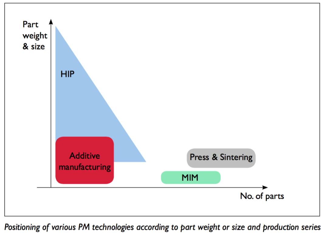
Fig. 2. Timeline of 3-D printing adoption curves (source Christopher Barnatt http://www.explainingthefuture.com/)
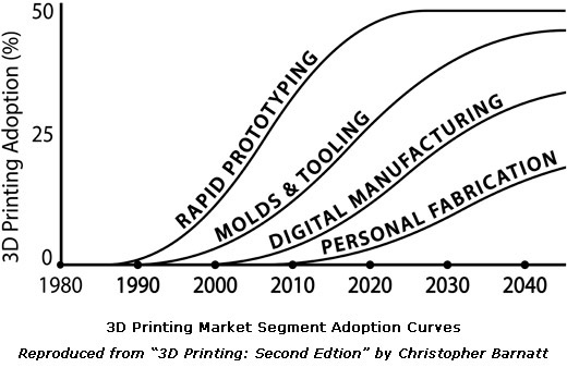
An example of an early adopter within the Automotive industry is Ford Motor; the company has been using this technology to develop prototype parts for test vehicles since the 1980s. With AM technology, Ford engineers have produced prototypes of cylinder heads, brake rotors, and rear axles in less time than the traditional manufacturing process would require [4].
In addition to Ford Motor, BMW uses additive processes to produce more than 100,000 parts a year for its vehicles. Turbomeca also uses metal AM for its serial production of helicopter engine components, as well as Selective Laser Melting (SLM) to manufacture fuel injector nozzles and combustion swirls for its engines. These engines are Turbomeca’s latest models and are claimed to be amongst the most advanced turboshafts ever designed [5].
Most popular powder metals use in AM are stainless steel, Inconel, magnesium, cobalt, titanium, copper, tool steels, and aluminum. Powder particle size has a direct influence on final part density, dimensional accuracy, and surface roughness. The smaller particle, the better final part quality. Non-weldable powder alloys cannot be processed by AM and challenging–to-weld alloys such as aluminum will require individual approach [6]. During additive process, layers of powder metal are added, melted and joined on top of each other until the final part shape and size is achieved. Recommended minimum wall thickness is usually 2 mm with a maximum length to high ratio shall not exceed 8:1 and minimum strut is 0.15 mm.[7]. For example, the SLM additive manufacturing process used by Turbomeca builds the components from a nickel-based superalloy powder in layers between 20 to 100 micron thick.
The ASTM International Committee on Additive Manufacturing Technologies has developed standard terminologies for AM. Below are the categories from the ASTM F2792 standard; four among them are suitable for metal AM (Table1).
TABLE 1
ASTM F2792 categories of 3-D printing

Even though AM offers the opportunity to reproduce most parts currently manufactured by conventional technologies such as milling or casting, only in some cases are the results better or cheaper than the original part. Parts densities of 99.9% are achievable, but still, there can be some residual internal porosities, cracks, high surface roughness, and impurities. Mechanical properties are usually superior to cast parts, but inferior to wrought parts [8]. Parts that need extensive machining after AM rarely will be competitive with traditional technology. Experience has shown that AM technology efficiency improves with smaller and more complex components. Fig. 4.4 highlights the break-even point for manufacturing, according to a study conducted by Atzeni and Salmi [9].

Heat Treatment for the Additive Manufacturing Process
During the AM process, defects, stresses, and anisotropic mechanical properties are induced due to columnar grain structures on the parts. These imperfections negatively influence the mechanical properties of the material, especially the fatigue behavior [10]. To achieve the necessary metallurgical specifications – such as surface quality, geometrical accuracy, and mechanical properties – AM parts are post-process by machining, EDM, grinding, polishing, heat treatment, and hot isostatic pressing, [11]. One of the processes that help improve the properties of AM parts is Hot Isostatic Press (HIP). HIP is a proven heat treatment technology that consolidates powder and removable porosities from the material. Also, the use of HIP high-pressure quenching avoids thermal stresses, deformation or cracking as compared to quenching with oil or water.
According to a metal powder manufacturer, vacuum furnaces must possess certain features to meet the requirements of AM processes, as summarized below [12]:
In addition to the above criteria, part size and production volume also affect and influence the effective vacuum furnace size.
Overall, the vacuum heat treatment process for AM manufactured parts is the same process as that of traditional subtractive manufacturing, and its purpose is to ensure AM parts have the necessary physical and metallurgical properties for specific applications. Heat treatment is essential for homogenizing the anisotropic AM parts’ structure and making it uniform. It is important that the heat-treated AM parts do not have surface or internal oxidation, decarburization or a discolored surface from water vapor, oxygen or alloy evaporation.
Vacuum furnaces with a non-contaminating heat treatment environment are required for thin wall parts. Stress relieving is commonly performed before parts are cut off from the platform. In some cases when a bidder is involved, the purpose of the heat treatment process is to debind and eliminate parts’ dimensional imperfections. Most vacuum furnaces use up to 800 ºC to relieve stress and then a higher temperature of up to 1,600 ºC for other processes. Using vacuum furnaces with high vacuum levels and the smaller hot zone is preferred for AM parts. Stress relieving, solution treatment and aging of parts made from alloys prone to oxidation require all metal hot zones.
AM parts made from titanium, cobalt and aluminum require vacuum levels of up to 10-6 mbar with 99.9995 argon purity with a dew point of 60C or better. Argon is the preferred gas because of its inert nature, as well as the fact that it has no adverse reaction with the alloy components. Creating an Alfa layer on titanium parts is not desirable and should be avoided.
Fig. 3. Ipsen furnaces at GE AM Pittsburgh facility (Source: Metal AM Magazine Spring 2016)

However, in spite of these recent advances in AM technology, the next challenge facing the heat treatment industry is determining how to integrate heat treatment into AM equipment so as to create one continuous process.
Another innovative way to print metallic parts is to use metal oxides, such as iron oxides (e.g., rust). Rust powder is lighter, cheaper and more stable to handle than pure iron metal. Northwestern University researchers discovered that they could first 3-D print structures with rust powder and then use hydrogen to turn green bodies into the metal before sintering it in the vacuum furnace [13].
Heat Treatment Diligence
The majority of parts manufactured by AM method will require debinding, sintering, annealing, stress relieving, aging, or surface modification process. Heat treatment’s challenge is to maintain the straightness, roundness, tolerances and material metallurgical properties of these parts. Minimizing the cost of the heat treatment is an important aspect of manufacturing, particularly during the additive manufacturing process. Below are several suggestions on how to enhance AM technics to optimize heat treatment cost:
Conclusion
As the heat treatment industry focuses on the integration of heat treatment and additive manufacturing into one continuous AM process, it is essential to remember the characteristics that make a vacuum furnace most suitable for AM processes. This include:
All too soon, industries can expect to see one-piece-flow heat treatment systems opening a new, efficient and controllable way to incorporate 3-D printing and heat treatment into the continuous manufacturing process.
References:
1. Composite Manufacturing Magazine , Article on website magazine October 15, 2014 http://compositesmanufacturingmagazine.com/
2. Metal AM Magazine 2016 Summer Edition, Inovar Commumication, Ltd, Vol2, No2, 6
3. Introduction to Additive Manufacturing Technology, A Guide for Designers and Engineers, European Powder Metallurgy Association 2015, 1st edition, 4.
4. Ford, Sharon. “Additive Manufacturing Technology: Potential Implications for U.S. Manufacturing Competitiveness.” Journal of International Commerce and Economics. Published electronically September 2014. http://www.usitc.gov/journals
5. Boulton, “Barbie, Auto Parts Hot of the Press,” June 6, 2013, B5
6. Introduction to Additive Manufacturing Technology, A Guide for Designers and Engineers, European Powder Metallurgy Association 2015, 1st edition, 6.
7. Introduction to Additive Manufacturing Technology, A Guide for Designers and Engineers, European Powder Metallurgy Association 2015, 1st edition, 29.
8. Introduction to Additive Manufacturing Technology, A Guide for Designers and Engineers, European Powder Metallurgy Association 2015, 1st edition, 24.
9. Atzeni, Eleonora, Luca Iuliano, and Allessandro Salmi. 2011. “On the Competitiveness of Additive Manufacturing for the Production of Metal Parts” 9th International Conference on Advanced Manufacturing Systems and Technology
10. J.Hjane, M.Ahlfors, Hot Isostatic Pressing for AM parts. www.Quintus.com white paper
11. Introduction to Additive Manufacturing Technology, A Guide for Designers and Engineers, European Powder Metallurgy Association 2015, 1st edition, 17.
12. http://www.metal-am.com/introduction_to_metal-additive_manufacturing/Secondary#sthash.hv6Z1Vgr.dpuf
13. Private discussion with metal powder manufacturer VVT.
14. Northwest team develop innovative method for metal Additive Manufacturing, Article from Metal AM, Vol2 No.1 Spring 2016;34
Janusz Kowalewski
Ipsen, Cherry Valley, Illinois, USA
Janusz.kowalewski@ipsenusa.com
Amazing Vacuum Furnaces – Price Trends
Considering the way vacuum furnaces are made today, the process is incredibly complicated and time consuming. Tons of machines and formed metal, graphite, composite and electrical parts are used to making the vacuum furnace. All these parts are connected, welded, glued, bolted or press-fitted to create one perfectly working vacuum furnace. The control system utilizes PLCs with sophisticated software and easy to follow graphic displays. Considering the above mentioned design complexity and added engineering and manufacturing know-how, it is very expensive to manufacture a vacuum furnace, and there is a steep learning curve for newcomers. The Asian companies are getting there slowly but only by replicating what more established companies are doing.
Today’s vacuum furnace design is the result of years of incremental change that has added to the complexity, robustness, and the furnace’s operational safety. The current price for the standard vacuum furnace is lower that it was couple years ago. It seems like the majority of vacuum furnace manufacturers were able to increase performance and lower capital costs at the same time. To understand why the price for a vacuum furnace is lower today, one needs to consider only two factors: the new disruptive business model and increased competition.
The new disruptive business model is being introduced in some part thanks to better material supply chains. The supply chain has become much more global, with sub-suppliers located in different places in the world. Communication and transportation costs are significantly lower compared to few years ago. We cannot overlook the ease of communication across continents between buyers and suppliers. This easy communication was not possible just few years ago. Tariffs, shipment restrictions, duties and customs clearances are much simpler or have been altogether eliminated. To compete in any market – European, Asian or American – a perfectly synchronize global supply chain is necessary to succeed.
Second, the business model of vacuum furnace manufacturers is shifting from selling manufacture to order furnaces, to the sale of standard or modular vacuum furnace. Various vacuum furnace manufacturers are including process softwares such as the carburizing or nitriding process technology in the standard future.
Competition is intense amongst furnace companies in each sub-segment of the vacuum heat treatment market. As the vacuum heat treatment industry matures, vacuum furnace costs and process softwares will emerge as primary differentiators. Closer collaboration with customers will be crucial since it otherwise would be difficult to develop solutions targeted to their particular needs. As an added benefit, collaboration with end users could give furnace manufacturers more insight into the decision-making process and technological process needs. Strategic partnerships with clients could also be important for individual furnace players, especially with R&D costs rising. For instance, furnace makers could shift to a business model in which their customers provide sales guarantees to develop a new vacuum furnace similar to airplane industry practice.
To be more competitive in a new business model and more customer-centric oriented, vacuum furnace companies are adopting a system in which more revenue comes from maintaining the installed furnace base and optimizing its performance rather than from selling new equipment. The percentage of revenue generated from aftermarket activities are growing for most vacuum furnace companies. This new trend is transforming the vacuum furnace making company into a more service-oriented one. Janusz Kowalewski
Amazing Vacuum Furnaces – Repeatability and Capability Tests
The difficult task in heat treatment operation is to control and eliminate heat treatment variables – temperature uniformity, heating rate, vacuum level, etc. In the quest for the highest quality results in material science current heat treatment standards are not tough or precision enough to satisfy the new quality expectations. Recently, I was attending heat treatment conference in Munich, Germany when Klaus Herbold from BMW Group gave a brutal assessment of the metallurgical variation happening in different furnace systems. The presentation was so much different from the usual presentations that we are so used to listen during heat treatment conferences (I need to admit that this criticism includes my own numerous presentations given at different heat treatment conferences). It was very refreshing to hearing and watching data after data of how badly furnaces performed and listen to his opinion that we are not doing enough as a heat treatment community to improve current heat treatment quality.
Luckily for us the new digital technology has the potential to unlock new ways of managing heat treatment process variables and enhance productivity in vacuum heat treatment operations. The new IT technology implemented into vacuum furnace control system combine with new standards for testing furnace performances may reasonably be an answer to Mr. Herbold needs.
For example, gear grinding operation is very costly to achieve a final dimensional tolerance requirement. The new requirement driven by NVH specification [noise, vibration, harshness] requires gears to be grinding instead of rolling to achieve high dimensional precision.
To eliminate heat treatment variation, new dynamic standards should be developed and used along traditional testing procedures such as temperature uniformity (ASM2750E), vacuum leaks (ASM2769), process parameters ASM2759 (1 to 10).
The purpose of new testing procedures is to assure a vacuum furnace ability to perform constantly within the same expected outcome range within specific time period. Example of two new tests to evaluate vacuum furnaces are repeatability and capability tests. Repeatability test aim is to verify that the furnace is able to reproduce process parameters such as vacuum level, quenching speed, heating rate constantly. Capability test aim is to verify furnace consistency in terms of distortion and microstructure during heat treatment or surface modification processes such as Nitriding or Carburizing.
Understanding and addressing customer needs more effectively is a key reason for a vacuum furnace company to achieve success in today’s more customer-centric heat treating marketplace. Janusz Kowalewski
Amazing Vacuum Furnaces – LPC Technology within Gear Industry
The growth potential
Vacuum – Low Pressure Carburizing (LPC) was introduced in the 1990s to carburize high-end transmissions components. New LPC technology provided numerous advantages that sparked interest amongst many car and OEM gear manufacturers. By 2015, more than 1500 LPC chambers have been installed around the world. Volkswagen, GM, BMW, Ford, CFA, Renault, Porsche, Honda, Hyundai, and Indian car manufacturers (although with some limits) such as Mahindra and Tata have vacuum Low Pressure Carburizing systems for heat treatment its car gearboxes. The majority of gear manufacturers like EATON, ZF, GETRAG (MAGNA), Hoerbiger, JATCO, AISIN SEIKI, AICHI KIKAI, SAGW, GREAT WALL, GKN, LINAMAR, and DANA use LPC processes for heat treatment gears. The new generation of transmissions such as the dual clutch (DCT) and six-eight-nine speed automated transmissions are all carburized with LPC technology.
Still, the LPC has much room to grow in the near future. According to industry estimations, currently between 25% -30% of gears are vacuum carburizing with LPC technology. Graph 1 shows the LPC status in 2014 and the estimation for 2019. Graph 2 illustrates the adoption life cycle for a new technology. Assuming that in 2015 vacuum carburizing market penetration reaches 25% to 30%, we are very close to a period of exponentially increasing demand for vacuum furnace systems with LPC technology.

Low Pressure Vacuum Carburizing for Gears Heat Treatment
The vacuum carburizing technology (LPC) combine with new generation multi-chamber furnaces has several distinct operational advantages in manufacturing gears:
In vacuum carburizing, it has been proven that acetylene offers better carbon efficiency compared to propane, because of its instability and higher carbon content per mole of gas. By using acetylene, densely packed loads, especially parts with complicated shapes, can be carburized at a highly reproducible quality. Process parameters like temperature and gas flow are selected according to part-effective case departments, carbon surface concentration requirements and the total carburized surface of the parts. To achieve a specified carbon profile, the carburizing is done in alternating steps for carburizing boost and diffusion, followed by a final diffusion step (See below Graph 3). The root-to pitch case depth ratio in gears obtained in vacuum carburizing is much better 90 to 95% compare to conventional carburizing methods, which is under 70%.

According to Dr. Herwig Altena and Frank Schrank’s article published in Gear Technology (March-April 2004), higher carburizing temperatures will not have adverse results on grain coarsening if the carburizing is performed within a specific time frame. “… By implementing vacuum technology, the increase of carburizing temperature can be applied without any limitations caused by the furnace… However, an increase in carburization temperature may not be possible depending on steel quality and other metallurgical factors. Detailed tests performed by V. Schüler … on standard fine-grain stabilizing rods have shown that if the aluminum and nitrogen levels of the steel are sufficiently high, a carburization temperature of 980°C at a holding time of 4–8 hours will not lead to grain coarsening. The maximum admissible share of grain coarsening is limited to 10% (see Fig. 4). This gives the possibility of achieving effective hardening depths of 1.4–2 mm by direct hardening without intermediate isothermal annealing….”
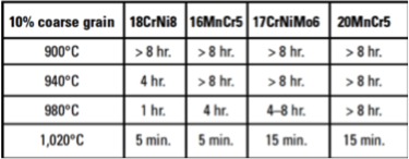
Grain growth vs. carburizing temperature and duration (after V. Schüler,)
Janusz Kowalewski
Ipsen, Cherry Valley, Illinois, USA
Janusz.kowalewski@ipsenusa.com
Amazing Vacuum Furnaces – Industrial Revolution 4.0 – A new eco-system for the agile gear heat treatment operation
According to a statement made by the American economist Wassily Leontief – “The industrial Revolution wasn’t very good if you were a horse” since the need for horses in the economy was eradicated when other forms of transportation and power were introduced. – So who will benefit from and who will be eradicated by Industry Revolution 4.0? Human labor – maybe? What is certain is that heat treatment operations will survive and prosper, but in a very different way compared to its current practice. To start off, lets concentrate on the multi chamber – Low Pressure Carburizing vacuum furnaces for gear industries.
Most automotive and gear companies are now able to digitally simulate their plant layouts and production processes in an effort to improve efficiency. The digital manufacturing processes could be an opportunity for furnace companies to compete with sophisticated software that controls and creates an entire Eco-System for gear manufacturers. The digitalization of the manufacturing process compels furnace companies to develop better software that expands beyond the traditional PLC/SCADA furnace controls functions. The operations of the multi-chamber Low Pressure Carburizing (LPC) vacuum system is highly computerized and cannot be efficiently operated manually. The new generation of multi chamber LPC vacuum furnaces for gear heat treatment requires highly sophisticated software to integrate furnace operations with the entire manufacturing process. This advanced furnace’s operational software allows for more synchronous monitoring processes and reduces human interference during operation.
New Predictive Maintenance software and sensors system installed in furnaces aim to reduce unscheduled downtime time to nearly none. This sort of predictive maintenance is particularly valuable in mass heat treatment operation, where any furnace breakdown causes damage to a valuable load, stops further downstream production, and disrupts upstream production’s schedule. It is far better for operators to be able to predict when a part will fail and replace it before it breaks down completely, or before the scheduled maintenance replacement.
The current multi-chamber LPC vacuum furnaces have numerous sensors across the entire heat treatment equipment that allows furnace integration into the entire manufacturing chain. In turn, this new software’s capability helps gear manufacturers enhance production speed and process quality. To adopt Internet of Things (IoT) into the factory setting, some furnace control systems will need to be upgraded or replaced to accommodate IoT sensors, gauges and actuators. Improvements in factory settings to accommodate connectivity and interoperability (for both machine-to-machine communications and for relaying large streams of data from the production floor) will also be required to adapt to IoT. This can be done by remote tracking, monitoring, and adjusting, based on the furnace operation’s sensor data from different furnaces performing heat processes across the entire gear production cycle.
Janusz Kowalewski
Ipsen, Cherry Valley, Illinois, USA
Janusz.kowalewski@ipsenusa.com
Amazing Vacuum Furnaces – How the Internet of Things Has Optimized the Future of Vacuum Heat Treatment Operations
The heat treatment industry is at a turning point, in which digital technology has the potential to unlock new ways of managing process variables and enhance productivity in vacuum heat treatment operations. Significant untapped potential for improving productivity lies in the adaptation of Internet of Things (IoT). The Internet of Things refers to the use of embedded sensors, actuators, and other devices that can collect or transmit information about the vacuum furnace operations. The greatest value-creating potential of the IoT is optimizing vacuum furnace operations through the data collection, data computation and maximizing production schedule. This mode of operation requires using sensors, rather than human judgment (and human error), to adjust the furnace’s operational parameters. In addition to optimizing operations, the next most valuable application of IoT in heat treatment is predictive maintenance adaptation and spare parts inventory. Predictive maintenance involves continuously using sensors to monitor furnace components’ performance to avoid breakdowns and to determine when maintenance will be required, rather than relying on regularly scheduled maintenance routines.
For example one of the main tenants of gear manufacturing’s lean manufacturing movement is to increase productivity by reducing the work in progress inventory. A type of system that fits these criteria is the new generation multi-chamber vacuum system. However, as the supply chain becomes leaner, it also becomes more vulnerable to production interruptions caused by equipment breakdown. In this situation, implementing predictable maintenance system is an important and necessary element to assuring seamless gear manufacturing. The tracking of furnace performance is essential in enabling sensors to real time sensing and tracking the heat treatment process parameters (such as vacuum level and temperature fluctuation, carburizing gas flow, time of each segments…etc.) and furnace conditions (such as vacuum pumps oil temperature, motors temperature, heating element amperage…etc.).
For IoT applications to be adopted in heat treatment settings, furnace control systems need to be upgraded or replaced to accommodate IoT sensors, actuators and software that can analyze the stream of data from sensors. It is also required to improve connectivity and interoperability between furnace control systems and plant ERP systems. The success and speed of adapting this new technology will depends on lowering the cost of the basic technology such as sensors, micro-electromechanical systems (MEMs), and cloud data storage and computing. IoT can improve furnace spare part inventory management as well by automatically ordering spare parts based on usage frequency.
Finally, capturing the value from digital innovations represents a fundamental shift in vision, strategy, operating model, and capabilities in the heat treatment industry. The path to improving heat treatment productivity will come through reducing technology costs and, where possible, eliminating the variability in heat treatment operations. For the full benefit of IoT in heat treatment industry to be realized, security needs to be addressed. Furnace operators need data to know how furnaces are operating and at the same time managers need to trust that the system is maintaining strict data security.
Janusz Kowalewski
Amazing Vacuum Furnaces – LPC Technology for Powder Metal Gears and Parts
Carburizing is one of the leading surface-hardening processes applied to the sintered, low-alloyed steel gears in the automotive industry. While diffusion of carbon in wrought steel is well documented, this is not the case for PM steel subject to carburizing in vacuum furnaces. In the article “Vacuum Carburizing Technology for Powder Metal Gears and Parts” presented in 2006 at the AGMA conference, Karol Kucharski and I presented results that show that the density of the powder metal is the main factor for the final carbon content and distribution. Also important for carbon case formation is the state of the surface of the part; either sintered with open porosity or machined with closed porosity.
Chemical composition 8620 P.M. and 8620 steel*.
| Material | C | Si | Mn | Ni | Cr | Mo | Cu |
| 8620 P.M. | 0.19 | 0.21 | 0.84 | 0.52 | 0.51 | 0.21 | 0.21 |
| 8620 steel | 0.21 | 0.323 | 0.81 | 0.57 | 0.54 | 0.20 | 0.20 |
*A standard TRS bars compacted at the pressure from 480 MPa to 1080 MPa, from the blend equivalent to 8620 steel to green densities 7.0, 7.1, 7.2, 7.3, 7.4 and 7.5 g/ccm where used for carburizing test.
During Low Pressure Carburizing (LPC) process is not possible to set the carbon potential and control case composition due to absence of thermodynamic equilibrium. Vacuum LPC the boost-diffusion empirical / computer simulated process is applied to control the surface carbon contend and carbon distribution in the case. During the first carbon boost the flow of the carburizing gas (C2H2) has to be sufficient but well below saturation point for 8620 steel is reach and before carbide formation begins to form. The first pulse with shorten time will avoid soot deposition and formation of the massive carbides. To accomplish this goal, the calculation of the proper gas flow rate and time according specific carburizing temperature have to be made. In the case of P.M. parts, the amount of carbon absorbed by the part’s surface can be few times higher due to additional internal surface created by pores present in the carburized case [1,2]. This amount will depend on the density of the 8620 P.M. part and the stage of the surface – “as machined” or “as sintered”. It is believed that enhanced gas diffusion after initial evacuation of the P.M. parts leads to faster carburization from within the pores, especially when pores are open – surface “as sintered” and interconnected – low density. Vacuum carburizing of PM materials is much faster than of solid steel. The most important factors are porosity and type of surface. In experiments conducted by Karol Kucharski, P.M. samples with lowest density and open porosity showed the dramatic increase of the surface carbon content up to 2.5% C and 3 times deeper case compare to 8620 steel parts. Massive carbides formation and increase of retained austenite in the 8620 P.M.sample was also observed.
[1] R. G. Weber: Vacuum Carburizing and Carbonitriding of Powder Metallurgy Ferrous Alloys (Powder Metall. Int. 15 (1983) [2] 94).
[2] Y. T. Chen, R. W. Kiefer, Jr. Pitney Bowes, Inc. Stamford, Connecticut, USA;:
Carburizing Of P/M Materials (Carburizing Processing And Performance, Proceedings on an International Conference, p. 199, July 12-14, 1989, Lakewood, Colorado, USA).
This post is dedicated to my friend Karol Kucharski PhD, Ontario, Canada. I hope you will fully recover very soon. Cheers Karol!
Janusz Kowalewski
Amazing Vacuum Furnaces – Hardening O1 Steel
Could vacuum furnaces with 10/12 Bar pressure quench successfully harden tool and die steel such as O1? The answer is yes, but the heat treatment should be carefully settled for this particular type of steel, including at the initial pump down to the high vacuum level of 10-3 mbar or better range to avoid surface decarburization. Heating should be performed at partial pressure of 0.15 mbar (Torr) Also, the cross section of the tool and die should be no more than 3-4” (75-100 mm) depending on furnace cooling capability. Normally, oil hardened steels such as O1 (C 0.90; Mn 1.20; V 0.20; W 0.50; Cr 0.50) need oil hardening and single or sometimes double tempering. However, today a single chamber high pressure quench furnaces are preferred for O1 steel especially for small tools and dies.
Hardening of O1 steel requires a change in structure from the body-centered cubic structure found at room temperature to the face-centered cubic structure found in the Austenitic region. The steel is heated to the Austenitic region of 790-815°C (1450-1500°F) and holds 30 min per 25 mm (1”). Martensite is formed when the steel is suddenly quenched at 10 Bar or higher with Nitrogen. This is a very quick and brittle structure. The cooling should stop at (100-125°F) and parts should be immediately tempered. Hardness Rockwell „C” as-quenched should reach 64/65.

You can soak at the proper heat for 2 hours per inch (25 mm) of thickness for each temper. Air cool to room temperature between tempers. The normal tempering range for this grade is 175-260°C (300 to 450° F) 63/58 HRC.
Hardenability, which is a measure of the depth of full hardness achieved, depends on the type and amount of alloying elements. Different alloys that have the same amount of Carbon content will achieve the same amount of maximum hardness; however, the depth of full hardness will vary between them. The reason for alloying steels is not to increase their strength, but to increase their hardenability – the ease at which full hardness can be achieved throughout the material. http://www.efunda.com/processes/heat_treat/hardening/direct.cfm
Janusz Kowalewski
Creating a Customer for Life – Just a Dream or Possible Reality?
The goal of any furnace company is to interact with its customers in a way that creates a Customer for Life. Visiting many captive and commercial heat treaters, and seeing so many different furnaces from different manufacturers in the same area, it is obvious that only a few furnace companies had created total customer satisfaction. In other words, only few furnace companies were able to deliver a great furnace and create a Customer for Life. Here are three simple suggestions that may help create a Customer for Life:
1. Design Furnace with Connectivity
Furnace connectivity is key to improving a furnace company’s interaction with its customers and helping the customers operate the furnaces easily. Furnace connectivity boosts the number of self-service options that help resolve a furnace problem quickly, assure communications to be more relevant, and deliver consistent customer satisfaction. The furnace with control system connectivity can drive furnace operation costs down, and is also necessary so that furnace companies can have more flexibility in responding to furnace problems and anticipating customer needs.
2. Assure Technical and Process Support through out Useful Life of the Furnace
To provide meaningful technical and process support, furnace companies should first understand how a consumer is interacting with a furnace and modify those interactions to improve the customer’s experience. For example, if a customer needs a new process, then the furnace company should have the ability to provide guidelines on how to best utilize the furnace for that particular process. The more a customer interacts with a furnace company, the more the furnace company understands what their customers want. The rapid rise of wearable technology and the Internet of Things represents the latest wave of touch points that will enable furnace companies to have positive and meaningful cooperation with the customer.
By providing customers technical and process support, furnace companies learn what the customer needs and wants. For example, a furnace company can help its existing customers branch into new businesses and services. This service extends the furnace company’s relationship with the customer, ideally to the benefit of both parties. In return, these services provide a path to a more interactive, more informative, and more valuable furnace company-customer relationship.
3. Improve Customer Competitiveness
“Money talks” and heat treatment is no exception to this rule (in a positive way, though). Helping the customer improve its technical and economic competiveness in the market place creates a lasting bond between the furnace company and its customer. If a furnace company provides a reliable and economic furnace that requires less maintenance, then the customer’s profits rise. The furnace company’s goal should thus not only be to sell the furnace but to help the customer with their heat treatment daily operations. A furnace company has the responsibility to help their customer succeed in the market place. And in the business world, success creates success.
By helping a customer become more successful, a furnace company creates a Customer for Life.
Janusz Kowalewski
Five Financial Ratios I Use to Runs my Company more Efficiently
A company could not be operated well based on account receivables – that’s a basic fact. With cash bills are paid. This is very true in every country and especially in developing countries where the rules of law, contracts validity and financial responsibilities are not very well defined. There are several ratios and financial tools that help track, understand and improve the furnace company operation. According to Bankrate.com, there are more than 150 financial ratios available for managers to monitor their companies. Here are my five financial ratios that may help you to better understand your company operation.
Gross Profit Margin ratio:
Gross margin ratio is a profitability ratio that compares the gross margin of a business to the net sales. This ratio measures how profitable a company sells its furnaces, pare parts and services. This is the profit from the sale of furnace that can go to paying operating expenses. Higher ratios mean the company is selling their furnaces at a higher profit percentage. High ratios can typically be achieved by two ways. One-way is to lower your cost of material, engineering and labor. The second way a furnace company can achieve a high ratio is by marking their furnaces up higher profit margin.
A company with a higher gross margin ratios mean that the company will have more money to pay operating expenses like salaries, utilities, rent and capital improvements and new development. Since this ratio measures the profits from selling furnaces, it also measures the percentage of sales that can be used to help fund other parts of the business.
Current ratio:
The current ratio is a liquidity ratio that measures a company’s ability to pay off its short-term liabilities with its current assets. The current ratio is an important measure of liquidity because short-term liabilities are due within the next year.
This ratio is extremely important for a small and newly establishes companies where the long-term investment does not exist and ability to borrowing money against collectable are very limited.
Account Receivable Ratio:
Account Receivable ratio is also called activity ratios measure how well companies utilize their assets to generate income. Activity ratios often look at the time it takes companies to collect cash from customer or the time it takes companies to convert furnace into cash—in other words, make sales. I use this ratio to monitor and to help improve the company manufacturing process by shortening the delivery time. Efficiency ratios go hand in hand with profitability ratios. Most often when companies are efficient with their resources, they become more profitable.
Return on Capital Employed Ratio:
Return on capital employed or ROCE is a profitability ratio that measures how efficiently a company can generate profits from its capital employed by comparing net operating profit to capital employed. The return on capital employed ratio shows how much profit each dollar of employed capital generates.
This ratio is based on two important calculations: operating profit and capital employed. Net operating profit is often called EBIT or earnings before interest and taxes. EBIT is often reported on the income statement because it shows the company profits generated from operations. The return on capital employed ratio shows how much profit each dollar of employed capital generates. Obviously, a higher ratio would be more favorable because it means that more dollars of profits are generated by each dollar of capital employed.
Book to Invoice Ratio:
Book to invoice is the ratio of orders received for furnaces to shipped and billed for a specified period, generally a quarter or six month. This ratio is my favorable because it is an indication of the performance and outlook for my company. A ratio of above 1 implies that more orders were received than filled, indicating strong demand, while a ratio below1 implies weaker demand. Also indicates the company the ability to efficiency build furnaces. Ratio well above 1, may indicates inability to build furnaces effciently or some of the furnaces are stuck during testing for unforsseble problems. Janusz Kowalewski
Amazing Vacuum Furnaces: Global Vacuum Furnace Market
Around 500 to 525 single chamber vacuum furnaces are manufactured annually worldwide. Approximately 15 multi-chamber systems are sold annually with ±90 chambers, plus 35 custom-made vacuum chambers, such as double chambers and special purpose furnaces. Most, if not all, vacuum furnaces are manufactured in these 12 countries: China, U.S., Germany, France, Japan, Poland, India, Italy, the U.K. Turkey, Taiwan and Canada. Some of the largest vacuum furnace builders are ALD Group-Germany, Ipsen-Germany/USA, IHI-Japan, Chugai Ro-Japan, ECM-France, Seco/Warwick-Poland, GM-USA, Tenova Group –Italy/France/Germany, Fendong-China, SIMUWU-China, Beijing Hua, – China, Solar Mfg.-USA, Centorr-US, and Vac Aero-Canada. For the full list, please go to Furnace Manufacturers page on this Global Heat Treatment Network website.
The table below describes the 30 biggest manufacturing countries with the most attractive markets for vacuum furnaces.

Source: Data from World Bank 2014 and Janusz Kowalewski
Some of the most innovative ideas introduced to vacuum furnaces in the last few months are: a dynamic gas flow, 150 mm curved heating elements, round one piece hot zone insulation with CFC hot face, gas heating, and 3 D control system. Each furnace design differs drastically in cooling speed therefore it is difficult and impractical to classify vacuum furnaces according to cooling pressure. Different vacuum furnaces will cool with different characteristics, even if they share the same cooling pressure. NADCA’s cooling specifications for block 400x400x400 mm (16”x16”x16”) is good for dies but for typical heat treatment loads, a new cooling specification/test should be developed by third and independent organizations such as the Center Heat Treatment Excellence in Wooster MA. One suggestion is that the cooling test should consists of 9 loading thermocouples that are already used for the temperature uniformity, and inserted into 9 inside rods with dimensions of 1” or 2” diameter by 12” long or even bigger, and located in the hot zone in the same pattern as the temperature uniformity thermocouples.
Janusz Kowalewski
Amazing Vacuum Furnaces: Some Important Details for You to Know
The long delivery items for vacuum furnaces are vessels, flanges, pumping systems, and cooling motors. The number of engineering hours required to design a non-standard single chamber vacuum furnace is between 500 to 3000 of Mechanical, Electrical Engineering and Project Management Hours. Depending on the labor classification and the percentage of fabrication outsourced, the amount of time it takes to fabricate and assemble a single chamber vacuum furnace can takes from 1000 to 3000 working hours. Most vacuum furnaces have standardized designs with similar dimensions. The standard dimension for vacuum furnaces manufactured by the majority of furnace companies in the US and Europe are:
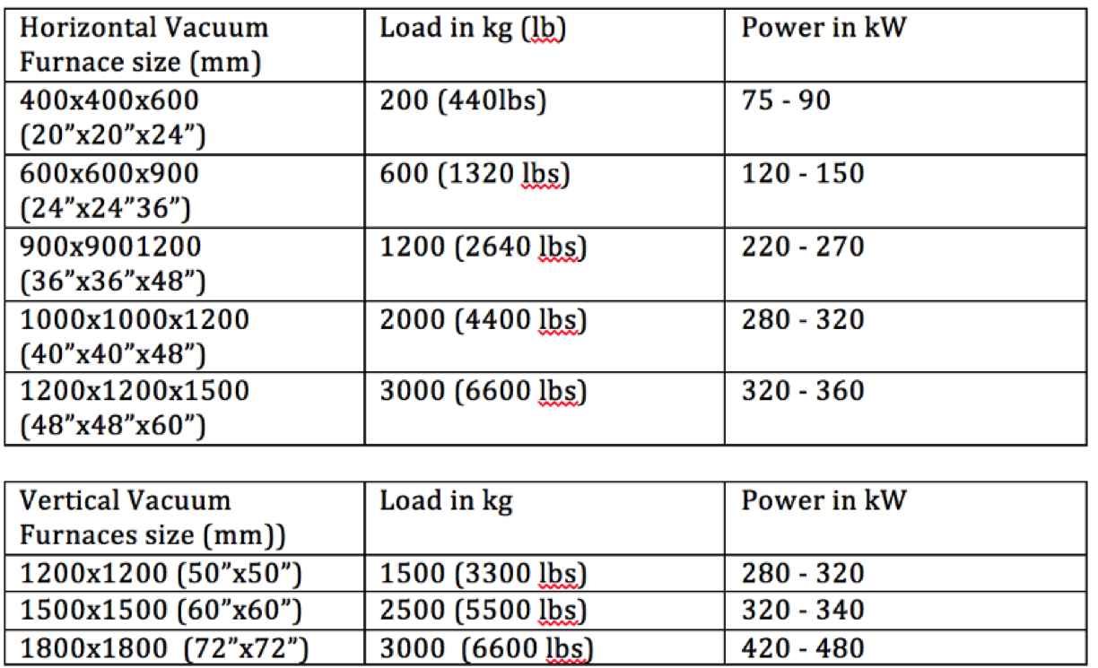
Most heat treatment vacuum furnaces with convection heating are operating from 150°C to 1320°C with good temperature uniformity (AMS 2750 E ±5°C) and vacuum levels in the range of 10-2 mbar (Torr) or with a 10-5 mbar (Torr) with diffusion pump. Special vacuum furnace temperatures may go as high as 3000°C and reach a vacuum level in the 10-8 mbar (Torr) range.
The table below describes the dimensions for a non-standardized vacuum furnace:

Janusz Kowalewski
Amazing Vacuum Furnaces: Disappointing Market Position of New & Better Technologies
The biggest heat treatment trade show of this year’s Thermoprocess, The Bright Future of Metals, occurred in Düsseldorf and had great press coverage. The next crown master will be the ASM trade show in Detroit in October and the Heat Treatment trade show in Beijing during September.
Companies that started off small couple years ago have grown larger and companies that dominated in 1990 are starting to take the back seats at these shows. The disappointing part of the show in Germany this year was how few new and exciting technologies were displayed. We have all read about the Internet of Things, we all use smart phones, and we’ve all heard of or own our own wearable technology, but heat treatment is slow in adopting these new technologies to make furnaces more efficient and predictable. These new technologies were all missing from the displays at the trade show. The most exciting displays were a one-piece-flow furnace, a concept pioneered by ALD, and a melting furnace door that automatically opened and closed.
When considering the number of vacuum furnaces with Low Pressure Carburizing compared to the number with traditional Sealed Quench furnaces and pusher furnaces, why has the adaptation of Low Pressure Carburizing in heat treatment industry been such a relatively slow process?
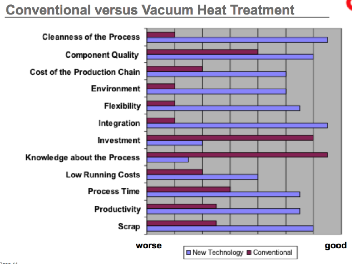
From this graph, it is obvious that the two major obstacles for accepting new vacuum technologies are the initial investment cost and the knowledge about the process. Capital costs are declining and interests are low, so the biggest obstacle is the lack of knowledge of the process since the Internet of Things has not penetrated the heat treatment market. This is because of two reasons. First, there aren’t enough real time carburizing sensors that allow heat treat treaters to monitor carbon case creation and the LPC is a computer empirically design process. Second, the people responsible for selecting new vacuum technologies are not familiar enough with vacuum technology and so they are reluctant to select something that is difficult for them to evaluate at the vendor and at their workplace. Some OEMs are more likely to choose well-known and proven technologies than to invest in novel technology.
Janusz Kowalewski
Amazing Vacuum Furnaces: Vacuum Air and Water Leaks in to Vacuum Chamber.
Until now, I have presented how important the vacuum furnaces are to the heat treatment industry. Today, we will discuss one of common event that is influencing negatively a vacuum furnace performance: air and water leaks into a vacuum chamber.
Air and water leaks to vacuum furnace.
Q1- Leak rate , V – vessel volume, dp/dt pressure rise over time.
Leaks to vacuum chambers (air / water leaks) cost thousands of dollars, creates countless technical problems for the furnace operators. There are two leaks that coexists in any vacuum system: the real and virtual leak. Real Leak is any path through the wall of a vacuum chamber that allows the air/gas to pass through. The Virtual leak is a source of gas in vacuum system that acts like a leak in that gas is trapped in a tight crevice, blind holes, porous welds and leaks out over a long period of time. (Source: AMS2769B) The root cause of these leaks is usually a manufacturing defect within the material or a lack of complying with good vacuum practice.
The below graph is presenting a both leaks. On the Internet there are thousands of articles regarding leak rates measure technique and suggestion how to find a vacuum leaks. Ones of the most difficult to find leaks are:
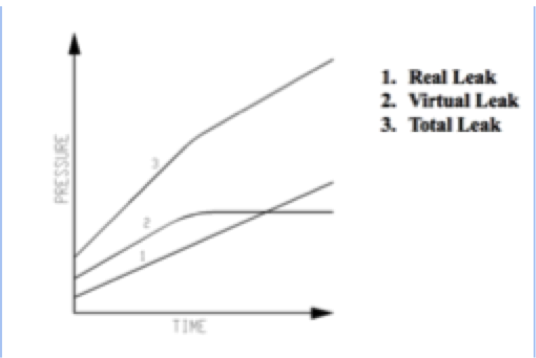
The furnace insulation, heating element and almost all other components within the furnace will be negatively influence by excessive leak rate. The most effective method to find leak is the Helium Mass Spectrometer. Leak test should be only performed after burn out cycle is performed and furnace is cold, clean, degassed, and empty. To learn more read AMS 2769 B. Paragraph 3.1.1.3 leak checking procedure.
Below is a graph presenting water leak into vacuum chamber through thermocouple port weld in the vessel chamber.

Amazing Vacuum Furnaces: Vacuum History
Vacuum word come from the Latin adjective vacuus for vacant and describes an empty physical space. The 2,500 years ago the Greek philosopher Demokrit thought the first time about and empty space (vacuum), but the famous Aristoteles denied such an idea and he thought about a special matter, what he called Ether. In the middle of the 17th century Torricelli made the first vacuum with mercury filled bended glass tube. Later Pascale prove of the possibility of vacuum with his famous test “vide dans le vide”, what means empty in the empty.
Otto von Guerike made a test with two hemispheres with a diameter of 42cm. The sealing was made of leather soaked with turpentine and wax. The evacuation was done by an air pump, developed by Otto von Guericke. The air pressure within the ball was ~ 100 mbar (75 Torr). In total 16 horses try to pull the both hemisphere, but they could not succeed, as they could not overcome the 13,850 N.
Vacuum Levels at:
Deep Space ≈ 10-17 Torr § Mars ≈ 5 Torr § Lunar Surface ≈ 10-11 Torr § Geosynchronous Satellites ≈ 10-11 Torr § Space Station (ISS) ≈ 10-9 Torr § >264,000 Feet (80.5 km) = U.S. definition of space flight ≈ 10-3 Torr § > 105,000 Feet (32 km) turbojets no longer function ≈ 8 Torr § < 40,000 Feet (12.1 km) cargo & passenger airline flights ≈ 141 Torr Source: Orbitec.com
Vacuum

Fig. 1. Vacuum pumps and the vacuum level.
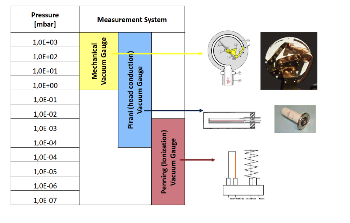
Fig. 2. Vacuum Gages for the Different Vacuum Requirements.

Fig. 3. Influence of vacuum level (Oxygen level) on metal parts discoloration.
For more information regarding vacuum level requirements for steel and alloys check AMS 2769B Specification, Table 1.
Janusz Kowalewski
Amazing Vacuum Furnaces: Low Pressure Carburizing
Demand for a higher quality and dissatisfaction with the existing vacuum carburizing processes were the main reasons for development of a new carburizing technology called – Low Pressure Carburizing. The advancement was due to the following achievements:

In the early stage of development in late 1960’s, vacuum carburizing furnaces were using Methane (CH4) as a carburizing gas. Carburizing technology base on Methane requires higher temperature and pressure up to 13 mbar (10 Torr). The process has not provided case uniformity or repeatability needed for parts specifications. Propane popularity in 1970 as carburizing gas was due to ease of transportation and worldwide availability. The major drawbacks of propane are tendency to create soot and tar because of thermal dissociation difficulty, poor holes penetration and problem with carburizing case uniformity in dense pack loads. The process with propane was run at 200–400 mbar (150–300 Torr). The environmental awareness, and a high furnace maintenance requirement was inspiration to develop a new process without the above problems. Russian scientists Krilow, Yumatow and Kubatow developed in 1979 a carburizing process using acetylene in vacuum furnace. The scientists patented process when acetylene is used for carburizing between 9 mbar (7 Torr) to 931 mbar (698 Torr) pressure. The Japanese company IHI (JH) patented in 1999 the low presure carburizing under vacuum with below < 3-mbar pressure. The latest achievements in vacuum carburizing are technologies using Acetylene (C2H2) for carburizing fewer than 20 mbar (15 Torr) pressures. The thermal dissociation of Acetylene last several seconds, enough to react with the hot load surface but not enough to create soot or tar on the furnace elements. The new low pressure vacuum carburizing is applied to a wide range of components from tiny precision parts to automotive gears and transmission components for aerospace, construction and machine industries.
To avoid tar/sooth formation, a vacuum carburizing process must be precisely established and maintain during the cycle. The main parameters influencing carburizing process are mass flow of carbon (gas flow rate), carburizing temperature, vacuum pressure, carburizing and diffusion durations stages. The parts in single chamber furnaces are usually heated by convection heating – up 750°C (1400°F) at 1.5 Bar Nitrogen pressure, follow by further heating in vacuum by radiation up to carburizing temperature. Time of heating and holding depends on particular cross-section, weight and density of load. The vacuum carburizing temperature depends on the alloy steel being treated and is typically between 930° C (1706°F) to 1050°°C (1922°F). When carburizing temperature is reached the carburizing gas is admitted into heating zone from numbers of jets located evenly throughout the entire hot zone. The number and location of carburizing nozzles ensures proper carburizing gas inflows and uniform charge penetration.
The carburizing process is automatically control by PLC/SCADA system.
Acetylene starts to decompose rapidly above 500ºC (932ºF). As the temperature increases decomposition of C2H2 accelerates to form atomic carbon. Hydrogen is a by-product of this decomposition resulting in the reduction of the metal oxides on the surface of components. Reduction of oxides on the surface leads to better penetration of carbon into the surface. The carburizing process can be continues (single pulse) or repeatable carburizing (boost) and diffusion steps (multi pulses). At the first stage the inflow of carburizing gas provide a very high concentration of carbon that can be absorbed by austenite. At the diffusion stage the inflow of carburizing gas is cut-off and replace by Nitrogen to keep constant partial pressure to prevent alloys sublimation. The free carbon atoms are allowed to diffuse into the part.

Diffusion reduces the carbon concentration on the surface and allowing for further carburization. The carburizing and diffusion stages are time controlled. The rapid and continue flow of carbon (gas flow) and higher process temperature shorten the carburizing process. As of today there is no sensor that could effectively control and measure carburizing case formation. Entire process is design by empirical knowledge.
Usefull information:
– Acetylene supply pressure: 1,5 bar pe (Europe, Asia); max.
0,9 bar pe (North America)
– Stainless steel pipe connection to furnace min. 1” (DN25) up to 50m length
– Customer has to follow local law for combustible gases if applicable
– For best result use of DMF dissolved Acetylene or Acetylene with 99.5% purity is recommended.
– Acetylene consumption for typical load for single chamber furnace:
| Load weight [kg] | Effective case depth [mm] | Load surface [m2] | [l/load] |
| 300 – 500 | 0,6 | 12 | 400 |
| 300 – 500 | 0,8 | 12 | 500 |
| 300 – 500 | 1,0 | 12 | 700 |
Janusz Kowalewski
Amazing Vacuum Furnaces: 10 Best Improvements Made to Vacuum Furnaces Throughout the Years
Amazing Vacuum Furnaces with Broad Process Flexibilities
Vacuum furnaces are designed to process parts that have complicated shapes with high dimensional accuracy. Today, is common to have brazing, austenitizing, quenching capabilities with martempering simulation and double tempering in the same vacuum furnace. Standard modern vacuum furnaces can cover an entire temperature range from 150°C to 1360°C. In the lower temperature range of 150°C to 700°C, the heat can be transferred by convection heating. In the temperature range from 600°C to 1360°C, the heat transfer takes place by means of radiation.
Vacuum furnaces with Nitrogen/Helium pressures reach up to 25 bar, a quenching intensity similar to that of the thermal hardening oils. So a broad range of widely varying material such as superalloys, high– speed steel, cold working steel, High Strength Low Alloy steel (HSLA) and medium-alloy tool steels can be heat treated in the vacuum furnaces. When there is a martempering simulation in quenching the distortion, cracking and the bulging a parts surfaces are minimized.
Brazing is a common process performed in vacuum furnaces. For example, parts that are designed for high thermodynamics, mechanical loading, and resistance to corrosion are commonly made from the material 1.4120 from two or more components. A low distortion, high temperature brazing process followed by a hardening and tempering process, is necessary because machining up later is no longer possible. The parts are first manufactured to 1 mm over production dimensions, mill and drill. Next, parts are annealed in the vacuum furnace and then reworked to within a 3/10 mm accuracy. The level surface must have a plane parallelism of 2 to 3/100 mm and perfect evenness. Surface roughness of 32 to 125 RMS adds surface area to the joint, which provides an extra capillary path for braze filler material to follow and straighten the braze joints. Next, the entire brazing and heat treatment process is carried automatically by PLC/SCADA control system in the vacuum furnace.
The cycle consists of heating, brazing, austenizing, quenching with martempering simulation and double tempering. End user records show that the braze part life increases on average from 300,000 pressing operations to 617,000 after switching brazing processes to run in the vacuum furnace. High temperatures in vacuum brazing and subsequent heat treatment reduces the distortion of the part as well.
For a guide on furnace brazing’s minimum equipment regulations and the process’ procedural requirements, follow the American Welding Society AWS C3.6M/C3.6 2008 specifications.
Janusz Kowalewski
How To Manage a Furnace Company in the Age of Connectivity
In the new age, where an economy of “sharing resources” plays an important role, new management styles are needed. The sharing economy is when renting, outsourcing and borrowing everything become on demand. In order to adapt to the sharing economy, companies need to create a better working organization to achieve total and absolute customer satisfaction. The traditional management styles in many global markets are not enough to sustain success and create new social capital.
The traditional management styles today are based on principles from the Babylonian, Mahabharata or Benedictine age. What has changed since this time is the speed that decisions are made, the speed of furnace delivery and the importance of total customer satisfaction. Because there is such high competition and the sharing economy allows customers to consider a wider range of companies, companies must focus on customer satisfaction. A company cannot succeed without it. This means that a company needs to not only respond to the customer’s needs, but also anticipate the customer’s wants. Success stories of this include Henry Ford and Apple. Henry Ford successfully created an entire automobile industry without asking customers what they needed, but managed to achieve total customer satisfaction with the Model T. Apple created a product that anticipated customer wants and increased the customer’s own self-satisfaction.
This principle should be converted and applied to the furnace business. Companies should shift their goal to achieving total customer satisfaction. Building a good furnace is not enough to succeed. There are many companies worldwide that manufacture good furnaces, but only a few provide total customer satisfaction. Good furnace performance, sound technological support and available after-sales support do not create an outstanding furnace company. The ability to create something of unexpected value that adds future or extra performance capability is what distinguishes an outstanding furnace company. The goal of the truly amazing furnace company is to provide equipment to the customer that will help the customer successfully compete in their market, lower their heat treatment cost, and improve the end product’s quality.
Outstanding furnace companies striving to be the world’s most connected furnace company with whole supply chain and customer base, and to create extra value futures that don’t just meet customer’s needs but amaze and delight their customers. Janusz Kowalewski
Efficient and Agile Heat Treatment Operations for Competitiveness and Growth
“Inexpensive goods can be produced even when workers are paid high wages”1
“The Principle of Scientific Management” by Frederick W. Taylor, 1911
Improvements in heat treatment technology and complementary changes in organizational structures are necessary to stay competitive in today’s worldwide market. Advancement in heat treatment technology is successful only if it is applied continuously to the entire heat treat process, equipment and organization structure. In order for the manufacturing organization to accept and practice continuous improvement, new organizational structures and new management concepts are needed. An agile organizational structure combined with the advanced digitalization of the manufacturing processes and new equipment based on PLC /IC (Programmable Logic Control / Industrial Computer) allows simplified operation and facilitate automatic diagnostics (routine and preventive maintenance) on the factory floor.
Importance of Equipment Layout, Sequence of Operation and Equipment Utilization in the Lean / Agile Manufacturing System.
The heat treatment process is ingrained in any manufacturing process, regardless of whether the heat treatment is performed in a commercial heat-treating shop or in an in-house heat-treating department. In many cases, efficiency in heat treatment has an important impact on the total efficiency of the manufacturing process and the scheduling and orderliness of the production flow. The following are general guidelines for designing an efficient heat treatment facility:
The challenges facing today’s heat-treating shops are numerous and could be divided into four groups: (1) equipment condition, maintainability and efficiency; (2) process suitability; (3) heat treatment shop layout and cleanness and (4) workforce experience. The equipment disconnection with process requirements is a major problem in achieving production efficiency. Optimizing the heat-treating shop layout requires careful consideration, time, and motion and material movement study. The payback from correctly operation layouts comes in form of reduction of operation cost and safety improvement. Heat treatment equipment layout involves locating the furnaces so that each task follows a pre-arranged route through a series of processes. The parts should flow along a line of processes that is clear, predictable and easy to control. The heat treatment equipment can be laid out according to process, cell production or product type.
Table 1: Layout Assessment
| Layout | Advantages | Disadvantages |
| Process | High mix, low volume and product flexibility Robust against disruptions Easy to supervise equipment | Low utilization of machines Can have high work-in-progress Complex flow can be difficult to control, |
| Cell | Good compromise between cost and flexibility for high-variety operations Fast throughput and traceability | More machines needed Can give lower equipment utilization |
| Product | Low unit costs for high volume Equipment can be specialized, improving efficiency Materials movement optimized | Low flexibility Not very robust to disruptions |
Source: FACTORY LAYOUT PRINCIPLES, Mark Allington, December 2006 3
An example of a layout according to process and cell production type is presented in the graph below, Graph 1. One-piece flow is gaining popularity in aerospace companies, where traceability is an important factor in production and quality system 4.
The carburizing process was incorporated into cell type production mode. By eliminating storage space, there was more space available and as a result, an improved product flow and traceability was achieved. In One Piece Flow (Cell Layout) gear, components are not heat-treated in conventional big batches with multiple layers, but they are processed in small batches. The One Piece Flow heat treatment provides
All the variations from layer to layer are eliminated, which leads to reductions in variations within the load. In addition, this new technology allows higher cost–savings for logistics. The manufacturing–line can be completely automated since the parts are first taken one by one from the soft machining unit, then heat treated in time with the cycle–time of soft machining (“Synchronized heat treatment”). Then, finally, the parts are passed down one by one to the hard machining unit5.
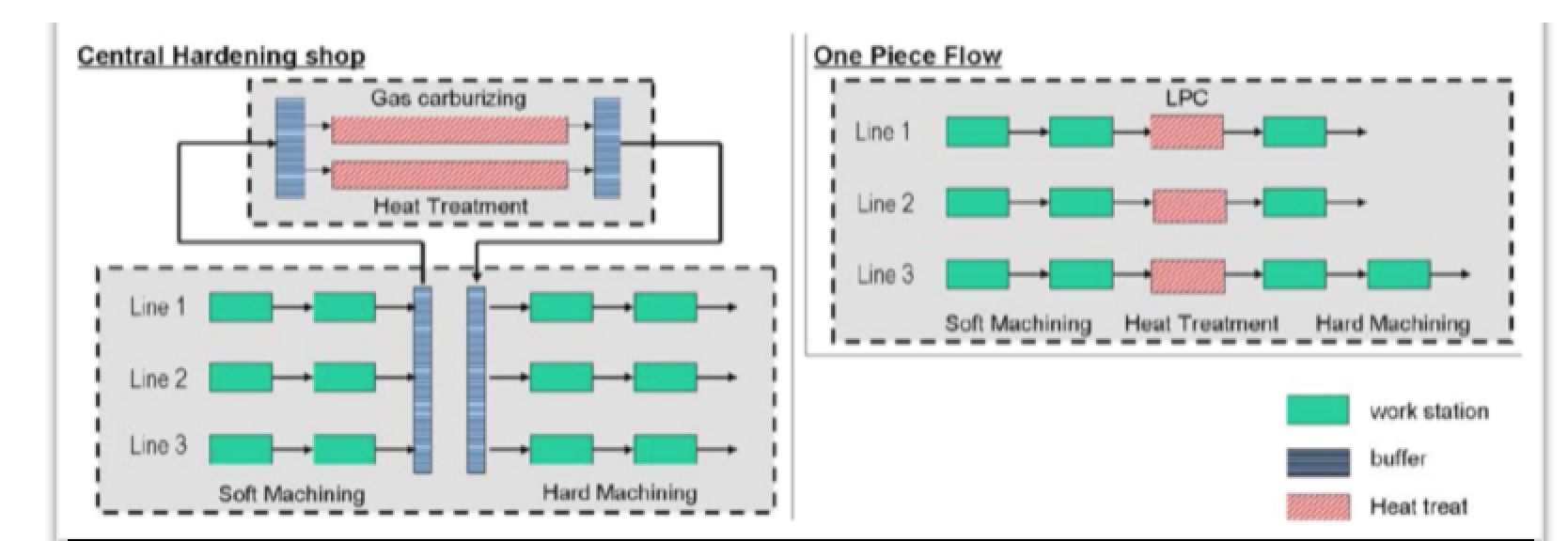
Fig. 1 Source: Enhance Distortion Control through One Piece Flow, Heuer… AGMA publication 20066
Table 2. Layout furnace and product compatibility
| Layout | Furnace Type | Sample Product Type |
| Process | Batch type furnaces: Sealed Quench, Bell, Box, Single or Double Chamber Vacuum furnaces | Middle size production lot such as mandrels,cutting tools, dies and molds, fuel injection nozzles, high end bearings, electric interrupters, pinions, aluminum coils, forging bars, airplane parts |
| Cell | Batch type/semi-continues: Sealed Quench, Box, Single Chamber Vacuum furnaces. | Small production lots. Semi finish parts, precision gears, shafts, saw blades, complex sub-assembly parts for machinery. |
| Product | Continues furnaces: Roller hearth, pushers, mesh belts, cast links, walking beams, Multi-chamber vacuum furnaces | Mass production parts such as fasteners, automotive gears, bearings, heat exchangers, PM parts, aluminum slabs and sheets |
Source: Janusz Kowalewski
Importance of New Ideas, Quality and the Human Factor in Agile and Growth Oriented Heat Treatment Operation
The future success of any manufacturer in the global market will depend on their ability to correctly implement organizational structure that effectively utilize employees, equipment and natural resources. This means that the success of a company depends on its ability to manage, control and direct resources to maximize manufacturing output. Additionally, quality should be built into every stage of heat treatment activities.
Even the largest and best heat-treating companies cannot succeed in the market without tapping into outside knowledge. The great success of Apple and other technology companies is their ability to draw technical knowledge from experts outside of their own organization. Employees are not the only sources of knowledge for the company. End users, universities and related businesses can provide necessary knowledge to compete successfully. Several years ago, research was conducted on the effectiveness of the engineering staff at the ATT Bell Lab organization. The most productive engineers did not differ from the least effective engineers by education or experience. The single source of difference was that the most effective engineers used the knowledge of several other engineers and established a large support group. Global Heat Treatment Network, Research Association of Industrial furnace manufacturers (FOGI) and ASM (American Society of Metals), play an important role in facilitating and improving interconnectivity between heat treaters worldwide and the newest process and equipment developments.
Management Systems That Increase Effectiveness of Heat Treating Operation
According to the John Boyd studies, a majority of companies will increase their productivity by changing the way they organize production and create “an organizational climate for operation success”7. Optimizing heat treatment equipment up-time, improving employee access to technical assistance and implementing an e-Kanban inventory reduction system will improve a heat treatment operation significantly.
Different management tools are used to increase effectiveness of heat treatment and problem identification such as Six Sigma, Quality Circles, Game Theory, etc. According to research conducted by Clayton M. Christensen and Michael Overdorf “…three factors effect what organization can and cannot do: its resources, its organization and its value.”8
Operation transparency and visualization of a heat treatment operation have the potential to significantly improve the company’s performance. Utilizing one of several computer software programs that are available for visualization of the furnace performance allows gradual cost improvement. Visual representation of the factory floor helps eliminate redundancy and provides Internet connectivity between the equipment and manufacturing processes. Visualization and flat organizational structure allow an efficient allocation of resources and by doing so will increase both the productivity and the competitiveness of the organization.
Continuously monitoring furnaces, washers, loading/unloading, cryogenic freezers, water, gas systems, and loading station allows timely problem recognition. Visualizing the furnace problem on an HMI display allows a faster respond time and more accurate problem definition. Intuitive skill and knowledge of the operation group will allow for more efficient allocation of resources and will increase productivity of the organization.
Lean / Agile Manufacturing Concept Applied to Heat Treatment Equipment
The ability to lower the cost of heat treatment could have significant cost advantages for manufacturers. Heat treatment can be an important competitive edge for any manufacturer that master heat treatment efficiency. According to study, part distortion for gear manufacturers runs in millions dollars per year for the additional cost of machining, scrap and extra material requirements to account for excessive distortion.
In order to increase the efficiency of the heat treatment process, furnaces should be integrated into the production flow of the manufacturing process. Integration is only possible if the control system of the furnace has communication capability with the facility ERP (Enterprise Resource Planning) and CMMS (Computer Maintenance Management System). The furnace integration with the company ERP and CMMS systems assures visualization of the heat treatment process. The goal is to simplify furnace operation and at the same time increase the reliability and efficiency of the furnace. The control system should have the following capabilities:
Furnace operations have changed drastically in the last 5 years. The next task is to design furnaces capable of automatic reasoning during the heat treatment cycle and provide solutions to furnace performance problems. Current development in the control system with PLC/Computer allows instantaneous communication with company production software. PLC/Computer base controls are designed to analyze furnace performance by monitoring all critical components such as vacuum pumps, valves, SCR, contactors, actuators, safety switches, heating elements, water flows, etc. Sensors monitor such parameters as motor vibration, motor temperature, motor’s electric power characteristic, water flow and temperature and heating element resistance. Data indicating parameters outside of the acceptable norm triggers an email or phone massage notification. The new e-manufacturing and lean manufacturing requirements do not make the furnace’s basic design in terms of heat treatment transfer, efficiency of insulation, and sturdy design less important. The “old fashioned” methods are still important, if not more important, for successful furnace operation.
The following are examples which principles should be considered in the equipment design stage:
The three main problems with furnaces on the factory floor are: (1) design, (2) workmanship and (3) operational faults. To eliminate the design and workmanship faults, strict testing is required. To eliminate the operator’s faults, training and “foolproof” control system are required. Each individual component and its subsystem should be tested to confirm their suitability for the task and how they will perform during operation. Testing processes should start from the individual component before it’s assembled into the sub-system. After the components are assembled into an operational sub-system, the sub-system should be tested. After all sub-systems are assembled into operating machines, the entire furnace should be tested. The final testing should be done by the equipment’s manufacturer in an environment as closed as possible to simulate the operational conditions of the end user’s factory floor.
In addition to technical furnace ability the following factors are also important:
The furnaces should be designed with minimum interface between the sub-system and components. A good indication of interface simplicity is the number of interconnecting cables between sub-systems. Another indication of simplicity is what a failed sub-system would do to the operation of the furnace. Will it disrupt the furnace operation completely or allow the furnace operation to continue?
New Vacuum Furnace Design for Agile Manufacturing
Advancements in Vacuum furnaces could be classified in several ways: First, improvement in furnace design, such as insulation improvement (lowering heat input per part or weight of the product) or improvements in heat transfer between the heat source and the load by utilizing combination of convection, conduction and radiation heat transfers. For example, in vacuum furnaces, the convection heating from ambient to 750°C (1400º F.) By combining radiation and convection heating, the heating cycle is shorted by 10% to 45%, depending on load configuration. Recent developments in Vacuum furnaces with gas heating system instate of electric resistance heating elements may lower the cost of operation for vacuum furnaces in the near future. Recent developments in gas burner controls allow them to overcome common problems with gas heating un-uniformly in the vacuum furnaces. The second advancement could be described in terms of operation improvement, such as the flexibility of the furnace, multipurpose furnace usage, self-diagnostic operational and maintenance simplicity. The ability to combine several surface modification processes, such as Carburizing /Nitriding, with traditional hardening or even PM Sintering significantly improve furnace operation and process cost. The third way is to improve the heat treatment process by changing technology; for example, changing a gasto the vacuum low pressure carburizing. Today’s vacuum furnaces are widely used for heat treatment such as annealing, de-gassing, de-stressing, aging (ageing), diffusion welding, sintering, brazing, sputtering, hardening, tempering, carburizing, nitriding and many other specialized processes. This list of applications is certainly not complete and, what more, some of the traditional technologies of heat treatment will change entirely to vacuum in the future. The best example from recent history is increasing the usage of Low Pressure Carburizing (LPC) technology for heat treatment of automobile gears.
Conclusion
Heat treatment equipment and control systems will change significantly over the next few years due to advancements in the Internet of Things, e-manufacturing and Agile Manufacturing requirements. These changes require careful planning, increased time, and a systematic approach to retooling the entire manufacturing operation. The new agile manufacturing principles allow fast and constant transformation of manufacturing processes to satisfy global customers’ wants and needs. The new worldwide market and redesigned factory floor requires employees to be capable of analyzing problems, formulating solutions and utilizing Computerized Artificial Intelligence to it’s maximum potential. Janusz Kowalewski
References:
1 Taylor, Frederick W., The Principle of Scientific Management (1911), W. W. Norton & Company, Inc., 500 Fifth Avenue, New York, NY, 1967
2 Richardson, Chet, Certain To Win: The Strategy Of John Boyd, Applied To Business, Xlibris, 2004, p. 51-57
3 Allington M. Factory Layout Principles, December, 2006
4 Pete Komrowski and Chris Marinucci, Improving Production Safely with Integrated Heat Treat and Quenching Cell Heat Processing for Gear Solution, Fall-Winter, 2013, p. 50
5, 6 Dr. Volker Heuer, Dr. Klaus Löser, and Dr. Thorsten Leist, ALD, and David Bolton, ALD TT Enhancing Control of Distortion Through ‘One Piece Flow – Heat Treatment’
7 Chester W. Richardson, A Swift, Elusive Sword: What if Sun Tzu and John Boyd Did a National Defense Review? Center for Defense Information, 2003, p. 64
8 Clayton M. Christensen and Michael Overdorf, Harvard Business Review on Innovation, Meeting the Challenge of Disruptive Change, 2001.p. 105
Industrial Revolution Version 4.0
Is your heat treatment equipment and organization ready for the 4th Industrial Revolution? This new industrial revolution – Industry 4.0 – is expected to bring major changes in heat treatment, production and how organizations are operated. It is believed there will be a shift from mass heat treatment operations to batch and one – piece flow production models. This is due to the increasing demand for customized products, the need for heat treatment process traceability, and a desire for lower prices.
The advancements in additive technology (3 D Printing) significantly speed up the customization process and how parts are heat-treat and integrated into the manufacturing process. In addition to accommodating the digitalization process (Industrial Internet), additive manufacturing offers several game changes in the field of: geometrical freedom, by allowing one to design new parts without traditional manufacturing constrains; create parts with precise designs customized for individual need; and reducing the amount of waste during the manufacturing process to almost nothing. For example, 20% of the additive manufacturing market arises from medical tools and parts. The new Industrial Revolution started in Europe.
According to a recent PWC study, German companies spend 50% of their capital investment on the digitalization of vertical and horizontal operations. This investment represents an amount of 40 billion Euros every year over the next 5 years. The PWC study shows a dramatic increase in spending on equipment connectivity and the digitalization of the organization process. To fully benefit from the world of the Industrial Internet and achieve a noticeable improvement in productivity by standardizing communication codes, there needs an assurance of communication data security. The digitalization of furnaces, process and service support is essential in sustainable organizational success and profitability.
In light of the shift to digitalization (Industrial Internet), how is this practically implemented in heat treatment process management and the equipment control itself? The key difference today compared to several years ago is the amount of sensors and software necessary to control the furnace in real time and the furnace’s communication with rest of the organization and even with the original furnace manufacturer. In a typical control system, the setting of the vacuum furnace operation is controlled by the PLC (Programmable Logic Controller) with a SCADA display. The furnace performance is supervised by process control software provided by the original furnace manufacturer. This system is connected through interfaces with the company enterprise resource ERP (Enterprise Resource Planning). The furnace control is also connected with furnace manufacturer and the operators via Smart Phones by utilizing a special design app. The special design software controls the furnace production schedule and sequence of the processes in order to fully utilize furnace time. When there is an alarm, an operator, or, in some instances, the furnace manufacturer receive a notification sent by the furnace control system. The use of software tools with text, video and audio ability has lead to significant furnace utilization improvements and time reductions in correctly diagnosing the problem’s root cause. The benefit of correctly applied Industrial Internet is magnified when all equipment in the shop floor are connected into one controlling and analyzing system. Advances in furnace control software and analytic techniques provide means to understand furnace performance conditions and optimize furnace efficiency. Connectivity among heat treatment equipment will enable enhanced asset reliability by optimizing preventive maintenance and repair processes. Are you ready for even bigger game changer – quantum computers? Janusz Kowalewski
Ten New Trends in Heat Treatment: A Global Perspective
Trend # 1:
Demand for heat treatment services and equipment is expanding at a higher global rate (5 to 6%) compare to rest of economic activities (0.5 to 1,5%). The high growth rate leads to an increasing number of furnace manufacturers expecially in Asia and creates intensive competition amongst furnace manufacturers.
Trend # 2:
An increasing usage of vacuum heat treatment technology. An increasing number of double and multichamber chamber vacuum furnaces with lights-out operation capabilities.
Trend # 3:
Increasing digitalization of the heat treatment operations. The growing trend of heat treatment integration into the manufacturing process (One Piece Flow Process). Increasing level of furnace controlability and mantainability by applying “Internet of Things” concept and systems integration.
Trend # 4:
Globalization of heat treatment standards, procedures, processes and furnace designs. Global equalization of heat treatment quality and furnace designs. Increasing importance of furnace safety operation with Zero Accident Furnace Design Philosophy.
Trend # 5:
Replacement of furnaces and technologies that generate high CO2 polution. Increasing importance of brazing, PM sintering and processes with shorten heat treatment cycle in heat treatment.
Trend # 6:
Increasing the importance of Nano and Thermo/Chemical Surface Modification processes. Replacement and modification of quenching mediums – Nanoquenchants, oil mist and vegetable oil.
Trend # 7:
Gradual dismay of mass heat treatment. Growing influence of 3 D Printing – Additive Manufacturing Method on heat treatment.
Trend # 8:
New Sources of Heat – Rotational Magnetic, Active Screen Plasma, Microwave, Laser and Infrared Heating.
Trend # 9:
Increasing sizes of sealed quench furnaces and we may see it decreasing usage of ceramic fiber insulation.
Trend # 10:
Markets with high growth potential for heat treatment – Mexico, India, Indonesia. New markets for future growth – Vietnam, Egypt, Ehtiopia, Ghana and Kenia.
Janusz Kowalewski
The Two Furnaces That Have Changed the Heat Treatment World Forever
The two furnaces that have changed the heat treatment forever are the Integral Quench and the Vacuum Furnaces.
Integral Quench Furnace:
In late 1940s, Herald Ipsen developed one of the first Integral Quench furnaces in the US. This new furnace revolutionized heat treatment technology by processing parts under a protective atmosphere and quench in oil. Decarburizing, scaling, and discoloration were minimized while metallurgical results reach new level…. Today, Integral quench furnaces are the most popular furnaces worldwide and are used in every corner of the world.
Vacuum Furnace:
The second furnace that revolutionized heat treatment technology was the vacuum furnace. In early 1910’s, two German companies – Leybold and Heraeus – independently developed the first industrial vacuum furnace with molecular and diffusion pumps. In 1916, Heraeus developed the first metallurgical furnace for melting chromium nickel alloys. Leybold started manufacturing industrial furnaces on a much larger scale in the 1930’s, and Degussa from the 1950’s. In the US a Rhode Island company C.I. Hayes built in 1940’s a first commercial vacuum furnace for RCA for degassing vacuum tube components. National Research Corp, NRC, a startup out of MIT started to build small Industrial vacuum furnace for very high temperature applications starting in the 1950’s. From there spun off Vacuum Industries and Brew and Abar in about 1960. In late 1960’s, a growing need for a vacuum nickel brazing for aircraft jet engine parts created a great demand for vacuum furnaces….
(It will continue…)
This was how it all began. Janusz Kowalewski
Future of the Heat Treatment:
Growing Technologies and Control System in Heat Treatment
The driving force behind developing new heat treatment equipment is reducing the environmental footprint, shortening production cycles, and lowering the cost of operation through more efficient utilization of utilities. The low temperature surface modification processes, with their low distortion attractiveness, will gain higher market shares. Nano Carburizing, Nitriding, Sulfonitriding, Low Temperature Vacuum Carburizing, and LPC are good candidates for a high growth potential within the next decade. Thermo-Chemical surface hardening processes such as CVD/PVD, Boronizing / Boriding will gain more acceptance. Processes with low NOx emission will be replacing the higher and more polluted processes. Vacuum technologies will gain market shares in the heat treatment. The major obstacle for more rapid growth of vacuum heat treatment is the high cost of equipment. As vacuum technologies mature, we can predict that the cost of manufacturing vacuum equipment will decrease. At the same time, the environmental concerns will justify higher costs of vacuum equipment compared to traditional furnaces with protective atmospheres. New sources of heat such as infrared heating and microwave assist technology will be more prevalent on the commercial scale.
Furnace control systems changed drastically in the last 10 years and the progress will continue. In order to increase the efficiency of the heat treatment process, furnaces will be integrated into the manufacturing production flow. Current development in the control system with PLC/HMI allows instantaneous communication with company production software. The goal is to simplify furnace operation, and at the same time increase the reliability and efficiency of the furnace.
The next task for a furnace control development is to design control systems capable of automatic reasoning during the heat treatment cycle and provide solutions to furnace performance problems. Janusz Kowalewski
Sticking problems during heat treatment in vacuum furnaces
A forum discussion, that took place some time back in which I participated, brought me to the idea to write an article about a phenomenon in vacuum heat treatment, called Sticking. Obviously an issue not always understood or not taken care of to avoid this by heat treating operators working on vacuum furnaces. Physical processes like sublimation, evaporation and solid-state diffusion contribute or are causing sticking problems, in fact parts contacting other parts or fixtures may stick together during vacuum operations. Another aspect not always considered during operating a vacuum furnace is the fact that friction coefficients in vacuum and at high temperature are higher than in air and ambient temperature, which may contribute to deformation. The first subject was raised by a heat treater who had problems with sticking problems when hardening high speed steel M4.
It concerned running rolls, up to 15 kg stacked on top of each other. The hardening temperature was 1190 ⁰ C in a vacuum furnace at a partial pressure of 1.2mbar. The question was whether anybody experienced this issue or has any advice on how to prevent the sticking. 45 years after introduction of vacuum furnaces in our heat treatment branch, I considered it remarkable that this issue in vacuum heat-treating operations might still be a problem. As a matter of fact it is a basic physical issue of solid state diffusion that occurs at elevated temperature when contacting clean parts are under a certain load and low vacuum pressure, atoms of one part diffuse into the surface of a contacting part, as such creating a bonding between both parts. When burrs or other irregularities are present on the contacting surfaces, like metal dust or small metal particles are slept in, having a high vapour pressure, this may cause sticking as well. According to table 1 at a hardening temperature of around 1200⁰C, if the partial pressure in the furnace is less than 1.3 x 10¯²mbar chromium will vaporize. Although the pressure chosen of 1.2mbar is not wrong, however obviously too low in the range to avoid sticking. It is often better to select a much higher pressure to reduce evaporation and sticking, also taking into account the tolerance thermocouples and pressure gauges may have. A partial pressure in the range of 5- 7 mbar or even higher, taking into account the weight of the rolls of 15 kg stacked on each other, it would be more reliable to avoid sticking. In the mentioned forum discussion, about 20 comments on this issue were brought in. To avoid metal/metal contact the majority of the forum members suggested to use magnesium oxide, brazing stop-off, alumina paint, boron nitride spray, Fiberfrax, binder free ceramic-and regular paper, mesh made of Kanthal and so on. Some of them work well others require cleaning after vacuum heat treatment or disintegrate. Instead of the risk of contaminating the pump oil or condensation of vaporized metal elements e.g. chromium on cold places in the vacuum furnace, I preferred to suggest to raise the partial pressure, at the same time to put small ceramic bars between the rolls. The intention was not only solving the sticking problem but also to improve more uniform cooling. By putting ceramic bars or plates between the rolls and between the bottom roll and the grid or basket as such creating separation of the metallic surfaces as well as creating space between the rolls improving more uniform and faster quenching the outside as well inside diameter.
An additional advantage of separating component surfaces by ceramic is lowering the friction coefficient, which in vacuum and at high temperature can be 2-3 times higher than in air and ambient temperature. An important issue because the general opinion is that vacuum hardening renders the least deformation, which is not always true. Why? Next time we will discuss this. Hans Veltrop
Table 1. Temperature (⁰C) at which specific vapor pressure (mbar) exists.
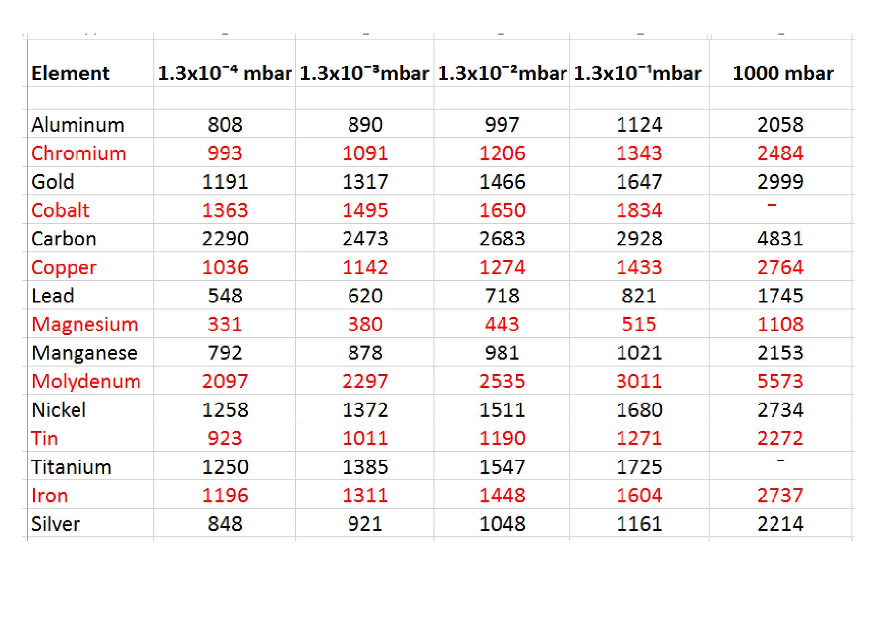
More than once I was asked what I was doing for a living and when I answered “heat treatment”, the person thought I was working on central heating systems in homes and buildings.
No one hit on the idea of e.g. steel and other metals and alloys to make them more durable as a tool or a construction part in machinery by heat treatment.
When asked how they thought about making products by tools or car components like gears in gear- boxes to withstand a 100.000 miles and more without making these wear resistant it was understood that without heat treatment we might still live in the early Middle Ages.
This introduction shows how many men and women in the street are aware of what heat treatment brought to them on comfort and allowing them to live a comfortable life.
Although according to archeologists evidence of steel hardening started 3000 years ago it lasted till the Middle Ages that alchemists described processes by which carburizing and nitriding have taken place obviously. Carried out by blacksmiths who annealed hot forgings in bird faeces and quenching knives and swords in boys urine, not knowing why, probably realized the first nitriding effect.
It lasted till the early 1900s when Machlet and Fry introduced the gasnitriding and use of ammonia and Flow published the two-stage process reducing the compound zone.
In 1932 Berghaus and Wehnheldt developed the plasma-or ion nitriding process
Saltbath processes were developed by ICI and later acquired by Degussa introducing Tenifer or Tufftride nitrocarburizing in the 50s.
These three base processes led to a large number of derivative processes developed later on during which over the last decennia the controle of nitriding processes have been optimized.
The large variety of processes and trade names created by commercial heat treaters and furnace builders however may create confusion and misunderstanding.
Why?
World trading and global sourcing of parts and products can create purchase specification problems.
In the past consultation between components- or service supplier and buyer, when near-by, national or international opposite to intercontinental was more extensive.
This gearing to one another often was not documented and more an unaware client service. This advising may be lacking in many occasions nowadays in particular when trading globally.
The consequence is that false expectations of norms arise as the requirements of the user may not be described in norms, e.g. steel parts to be surface hardened
The purchase order often contains only the name of a heat treatment e.g. nitriding or nitro- carburizing and a reference to a norm and price & delivery conditions. The required profile of the properties for supplying is often not clear and established. Manufacturing, processing, delivery according to a certain norm guarantees normally a standard quality.
The requirements regarding the properties of the heat treatment are sometimes more comprehensive than the standard quality.
Specifying Requirements
There are standard norm systems globally, covering all kind of details on the processing of nitriding and nitrocarburizing however many individual suppliers prefer to keep their processing confidential.
Therefore besides referring to a norm it is essential to specify certain or better specific requirements on max. temperature, required structure, surface hardness, effective nitriding depth and so on.
Confusion
Since some decades tremendous developments on diffusion processes like nitriding, nitro- carburizing and surface engineering (Coatings) have seen daylight and implemented into the heat
treatment world. Almost all furnace suppliers and commercial heat treatment shops with or without own input, trademarked their processes. The consequence is that people, not involved in heat treatment, are not aware what is behind the fancy proprierty names.
Global sourcing has increased the confusion buyers and design engineers experience.
It is not sufficient to refer only to existing norms, as they may not reflect what is needed.
Culture and language differences may increase mutual misunderstanding.
Temperature ranges of Nitriding / Nitrocarburizing (2)
Low Temperature Nitriding / Nitrocarburizing for stainless steels Max N 450 ⁰C, C 550⁰ C
Nitriding: Class 1/ Class 2 (Floe process) 500-565⁰ C
High/Low pressure
Oxynitriding, Sulfonitriding, Oxysulfonitriding 510- 580⁰ C
Ferritic nitrocarburizing 550- 585⁰ C
Austenitic nitrocarburizing 595-720⁰ C
High temperature nitriding 700- 800⁰ C
Solution nitriding of stainless steels 1050-1150⁰ C
If the core hardness is important, tempering of pre heat treatment should be about 30⁰ C higher than the nitriding/nitrocarburizing temperature
For Classic nitriding single and two-stage the norms are clear also for no experts.
SAE AMS 2759/6 specifies the nitriding of low- and higher alloy steels by the use of ammonia and dissociated ammonia.
Single-stage (class 2) nitriding requires a nitriding at 500-525⁰ C and a dissociation rate of 15 to 35%
Two-stage (class 1) nitriding (Floe process) requires a first stage at 500-525⁰ C and a dissociation rate of 15 to 35% and second stage at550 to 575⁰ C and a dissociation rate of 65 to 85%
SAE AMS 2759/10A specifies the nitriding potential to be used instead of the dissociation rate. The specification limits the compound layer thickness in AMS 2759/6 in the same way but adds class 0, where no compound layer is permitted.
Nitriding is carried out in following media:
Gas Nitriding at atmospheric,-low or high pressure in just ammonia with or without addition of nitrogen and or hydrogen. In ammonia with or without nitrogen, oxygen (oxynitriding), sulpher- compound (sulfonitriding)
Plasma as Ion nitriding, DC plasma, Pulsed plasma and Active screen with nitrogen as processing gas with or without hydrogen or argon
Pack nitriding
Nitrocarburizing processes are carried out in:
Aerated salt baths diffusing nitrogen and carbon into the steel, quenching in oxidation baths and polishing operations in between and subsequently oxidized in an oxidizing bath.
Sulpher containing salt baths.
At atmospheric pressure in ammonia and hydrocarbon or endothermic mixtures, post oxidation, with or without quenching and polishing operations.
Plasma nitrocarburizing adding nitrogen and carbon into the surface.
Nitrotec, Nitemper, Deganit, Soft Nitriding, Triniding, Nitroc, Vacuum Nitrocarburizing, Controlled Nitrocarburizing, Nitro Wear, Corr-i-dur, Oxycad NT
And many more!
Nitreg Potential-Controlled Gas Nitriding
Nitreg –C Potential-Controlled Gas Nitrocarburizing (FNC process)
ONC In-process Post-Nitriding/Nitrocarburizing Oxidation
Nitreg -S Potential-Controlles Nitriding of Stainless Steel
Nano-S Potential-Controlled Nitriding of Stainless Steel with better corrosion resistance
New Nitreg -Ti Nitriding of Titanium Alloys
Black-Tride Post-Nitriding/Nitrocarburizing Oxidation
Plasma (Ion) Nitriding
Sulfinuz, Sursulf, Tufftride, QPQ, KQ-500, SBN, Nitride, Nutride, , Melonite, Meli 1, Isonite, Palsonite
And many more!
Oxinit, Fernit, Plasox, Plastek, Planit, Ultra Glow NC, Nivox LH
And many more!
NITROTEC, KOLENE QPQ, IE.NU-TRIDE, LINDURE,NQ40, NITEMPER, ALLNIT, OXYCAD, TRINIDING,
NITROC, MALCOMIZING, NITRAL, NITREG,CORRIDUR, NITROCARBURIZING, FNC, ANC, NIVOX 2,
NIVOX 4, EXPANITE L, EXPANITE H, SUPEREXPANITE, LOW PRESSURE GASNITRIDING,LINDURE, NAKAL CATALYTIC NITRIDING, OXYNITRIDING, SULFONITRIDING, OXYSILFONITRIDING, PULSED PLASMA NITRIDING, ACTIVE SCREENNITRIDING, NITRAFI, NITROLOX, SOLNIT, IONIT-OX,MALONITE, TUFFTRIDE, ARCOR, NUTRIDE, N-QUENCH, DEGANIT, SOFT NITRIDE, NITRO WEAR, OXINIT, FERNIT, PLASOX, PLASTEK,PLANIT, ULTRA GLOW NC, NIVOX LH, SULFINUZ, SURSULF, KQ-500, SBN, MELI 1, ISONITE, PALSONITE,VACUUM NITROCARBURIZING, CONTROLLED NITROCARBURIZING
What’s in a name!
To get what you want and need you should specify, functional properties such as wear-, fatigue- and corrosion resistance.Important properties of the compound layer are: structure, chemistry, hardness and hardness depth.On the diffusion zone: hardness and depth.Steel properties as supplied: alloy composition, heat treatment condition and core hardness before nitriding / nitrocarburizing.
Based on the above the process parameters are to be defined: such as temperature, time, nitriding potential and gas composition.Quality control at the end should verify to what extend the results meet the specification and the required functional properties.Based on the foregoing it would be an advantage when suppliers of heat treatment processes give some more background info to make selection for buyers and design engineers easier. Hans Veltrop
1). Excerpt of a presentation given earlier at the Nitriding Summit, Wroclaw 8.10.2014
2). Courtesy of Karl-Michael Winter; Process-Electronic GmbH
This morning I read in my daily paper that it is expected that at this fall a number of casualties will be lost due to CO poisoning in their homes starting up their heating system now again as it becomes colder. Lack of professional maintenance is often the main cause that the heating system is dirty or out of balance with the consequence that incomplete burning of the hydrocarbon gas is taking place producing Carbon monoxide.
In chemistry class on high school we learnt that carbon and oxygen are essential elements that rule our being. We never realized that a difference of just one atom in composition of a chemical compound may be a healthy or a deadly issue.
CO is: colourless, poisonous, very inflammable, some lighter than air, odourless and tasteless, large diffusion power and in air mixture explosive. All IQ’s, chamber- and pit furnaces in which CO containing process gases are used, leak CO into and raise CO content in the working area when not adequately ventilated, caused by:
International regulation is diverse concerning what is allowed in working areas.
Mac-values which might be slightly adjusted meanwhile are:
In case of the following CO values, actions to be done and consequences are:
In case of peak values to stay in an environment is limited:
The above values mean in fact that workers on the shop floor when in case of higher CO values are exposed to working conditions that are unhealthy and that their functioning may be less alert and might lead to wrong decisions. As such it is not only a health & safety issue but an economical and quality issue as well.
Fact is that circumstances which cannot be tolerated and in practise occur have been shown by an international investigation on working conditions in western state of the art heat treatment shops of which 40 % showed high and far too high CO contamination in the working zone.
The reason that these circumstances occur is the sneaky properties of CO and in many cases is not recognized by the management of heat treatment shops. To get insight in this phenomenon is simple by installing cheap analysing equipment in the vicinity of heat treatment equipment, measuring and monitor the CO ppm in the air by which corrective actions can be taken.
I remembered the results of this investigation when I read a column on the site of the “Monty” in June in which the question was raised on the future of heat treatment and to what extent the Japanese model should be followed, in fact the discussion on furnace emissions.
Because of the importance of the issue, I copy the article in full with permission of “The Monty”:
The Future of Heat Treating (will we be following the Japanese model)? Over the years we have asked a number of very experienced heat treaters what they expect the industry to look like in the future. While we have heard a number of ideas none of them (with all due respect) were very definite or “earth shattering” for the obvious fact that none has a crystal ball to the best of our knowledge. A fellow the other day though did have a very definite opinion, an opinion which we didn’t particularly like but one which we feel is quite possible furnace emissions. The current almost cult like, fanaticism about greenhouse gas emissions causing global warming (or global changeor whatever it seems to change daily) shows no sign of abating in the near future and the recent decision by the US to work towards closing down coal fired power plants is a perfect example of this (we do agree that reducing pollution is a very worthwhile cause but greenhouse gases are another story in our humble opinion). A recent visit to Japan showed that heat treaters there are constantly trying to reduce all forms of furnace emissions and energy usage with the result that most of the atmosphere furnaces we saw have vacuum purge chambers on both the load and unload stations specifically to trap all emissions. While Japan has taken the largest steps towards this no issue parts of Europe appear to be going this direction also leaving North and South America as the outsiders. All of this takes us to this point; will North Americans be forced within the next few years to be equally as concerned with reducing green- house gas emissions? Far fetched as it might sound our understanding is that one of the largest captive heat treaters in North America has already mandated that all atmosphere furnaces will be shut down within 5 years to be replaced by vacuum carburizing units. We at “The Monty” believe that the only way emissions can be reduced are by switching to vacuum furnaces, expensive modifications toatmosphere furnaces or by converting all gas fired furnaces to electric which of course only pushes the issue down the road to the electrical suppliers. Perhaps it might be far fetched but it is also possible that within a few short years this will become a major issue and we in North and South America will all be looking towards Japan and Europe for suggestions. While we would find this an incredible waste of time and money stranger things have certainly happened. The future? Perhaps. June 26/2014″ End of the Monty article
Although I fully endorse the opinion of ‘The Monty”, I am the opinion that a difference should be made between emissions due to energy usage and atmospheric related emissions.
The solution on energy emissions are still a long way to go whereas emissions due to process atmospheres can be easily accomplished by evacuating before loading and de-loading as described above, but I expect after many attempts in the past, developments recently revealed by S.Bischoff of ROHDE Schutzgasöfen GmbH in Germany in cooperation with IWT Stiftung Institut für Werkstofftechnik,Bremen-Germany but also a promising project of Air products and Chemicals Ltd and inventer Zbigniew Zurecki et al, are quite promising to reduce CO₂ and CO emissions from furnace atmospheres by absence of oxygen in mixtures of just nitrogen and hydrocarbons at the same time reducing IGO.
After all it is remarkable that a difference of one atom of oxygen in a molecule CO which by lack of one oxygen atom causes that our blood is incapable to transport the oxygen to our vital organs and may cause dead, whereas an additional oxygen atom in the molecule CO₂ is needed to bring us so much joy drinking beer with a nice foam on it or making champagne sparkling and to finish this blog on a technical manner CO₂ is used to stop a fire; very remarkable but we have to live with it.
Hans Veltrop